
A position accurate auxiliary device for diode pin welding

An auxiliary device and diode technology, which is applied in the direction of assembling printed circuits with electrical components, can solve the problems of pin deviation or looseness in pin jacks, inability to solder pins firmly, short circuits, etc., to prevent offset, save solder, Avoid the effect of mutual short circuit

Active Publication Date: 2021-08-17
HEBEI UNIV OF ENG
View PDF0 Cites 0 Cited by
  • Summary
  • Abstract
  • Description
  • Claims
  • Application Information

AI Technical Summary

Problems solved by technology

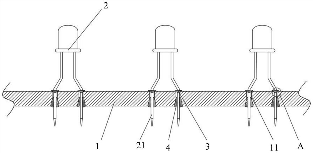
However, this welding method has certain defects in the actual use process. For example, due to the large hole diameter of the pin hole, the position of the pin is prone to deviation or loosening during welding. When soldering the pin, due to the deviation Or loosening will cause the fixed amount of solder during welding to fail to weld the pins firmly, and there will be a phenomenon of virtual welding. If the solder is repaired again, the solder is too large to easily touch the circuit wire next to it, causing a short circuit

Method used


Image

  • A position accurate auxiliary device for diode pin welding
  • A position accurate auxiliary device for diode pin welding
  • A position accurate auxiliary device for diode pin welding

Examples


Embodiment Construction

[0045] The following will clearly and completely describe the technical solutions in the embodiments of the present invention with reference to the accompanying drawings in the embodiments of the present invention. Obviously, the described embodiments are only some, not all, embodiments of the present invention. Based on the embodiments of the present invention, all other embodiments obtained by persons of ordinary skill in the art without making creative efforts belong to the protection scope of the present invention.

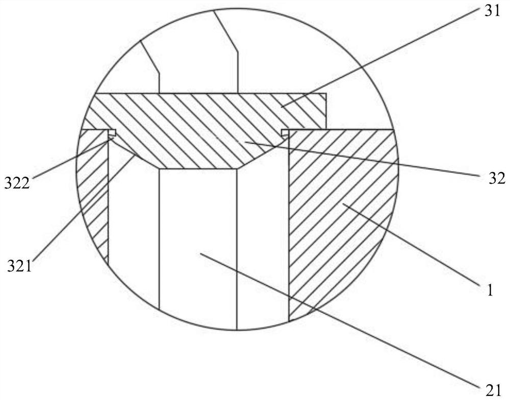
[0046] According to an embodiment of the present invention, a position accurate auxiliary device for diode pin welding, such as Figure 1-4 As shown, a position-accurate auxiliary device for diode pin welding includes: a circuit board 1 and a limiting part 3; a pin jack 11 is provided on the circuit board 1, and the pin 21 of the diode 2 is placed in the pin jack 11 In the middle; the inner wall of one end of the pin socket 11 filled with solder 4 is provided ...


PUM


Abstract

The invention discloses a position-accurate auxiliary device for diode pin welding, which comprises: a circuit board and a limit ring; pin jacks are provided on the circuit board, and diode pins are placed in the pin jacks; The inner wall of one end of the pin insertion hole filled with solder is provided with a first tapered edge inclined away from the center of the hole from the inside to the outside; the limiting part is sleeved on the pin and fixed on the The pin insertion hole is away from the end of the first tapered edge. The setting of the limiting ring and the first tapered edge on the circuit board in the present invention makes the position of the pins stable, the welding effect is good, and the solder is not easy to leak, and will not affect other circuits.

Description

technical field [0001] The invention relates to the technical field of diode installation, in particular to an auxiliary device for accurate position welding of diode pins. Background technique [0002] Diode is one of the most commonly used electronic components. Its biggest characteristic is one-way conduction. At present, light-emitting diodes are widely used in indicator lights of various electronic products, light sources for optical fiber communications, indicators of various instruments, and lighting. [0003] When using the diode, the pins need to be welded on the printed circuit board. At present, when welding the diode, in order to facilitate the insertion of the pins, the aperture of the pin jack is generally set to 4-7 times the diameter of the pins. However, this welding method has certain defects in the actual use process. For example, due to the large hole diameter of the pin hole, the position of the pin is prone to deviation or loosening during welding. When...

Claims


Application Information

Patent Timeline
Patent Type & Authority Patents(China)
IPC IPC(8): H05K3/34
Inventor 朱巧芬石亚杭张若雅罗粤浩徐基科朱项妤闫丹张雷门高夫
Owner HEBEI UNIV OF ENG
Learn More