Supercharge Your Innovation With Domain-Expert AI Agents!

Filter device

A filtration equipment and filter technology, applied in filtration separation, membrane filter, fixed filter element filter, etc., can solve problems such as mud clogging, and achieve the effect of effective cleaning, reduced pressure loss, and simple equipment structure

Active Publication Date: 2019-06-28
HYDAC PROCESS TECH
View PDF12 Cites 0 Cited by
  • Summary
  • Abstract
  • Description
  • Claims
  • Application Information

AI Technical Summary

Problems solved by technology

In addition, this configuration presents the risk of clogging of the mud discharge due to deposits, especially at the backwash connections in the valve arrangement

Method used


Image

  • Filter device
  • Filter device
  • Filter device

Examples


Embodiment Construction

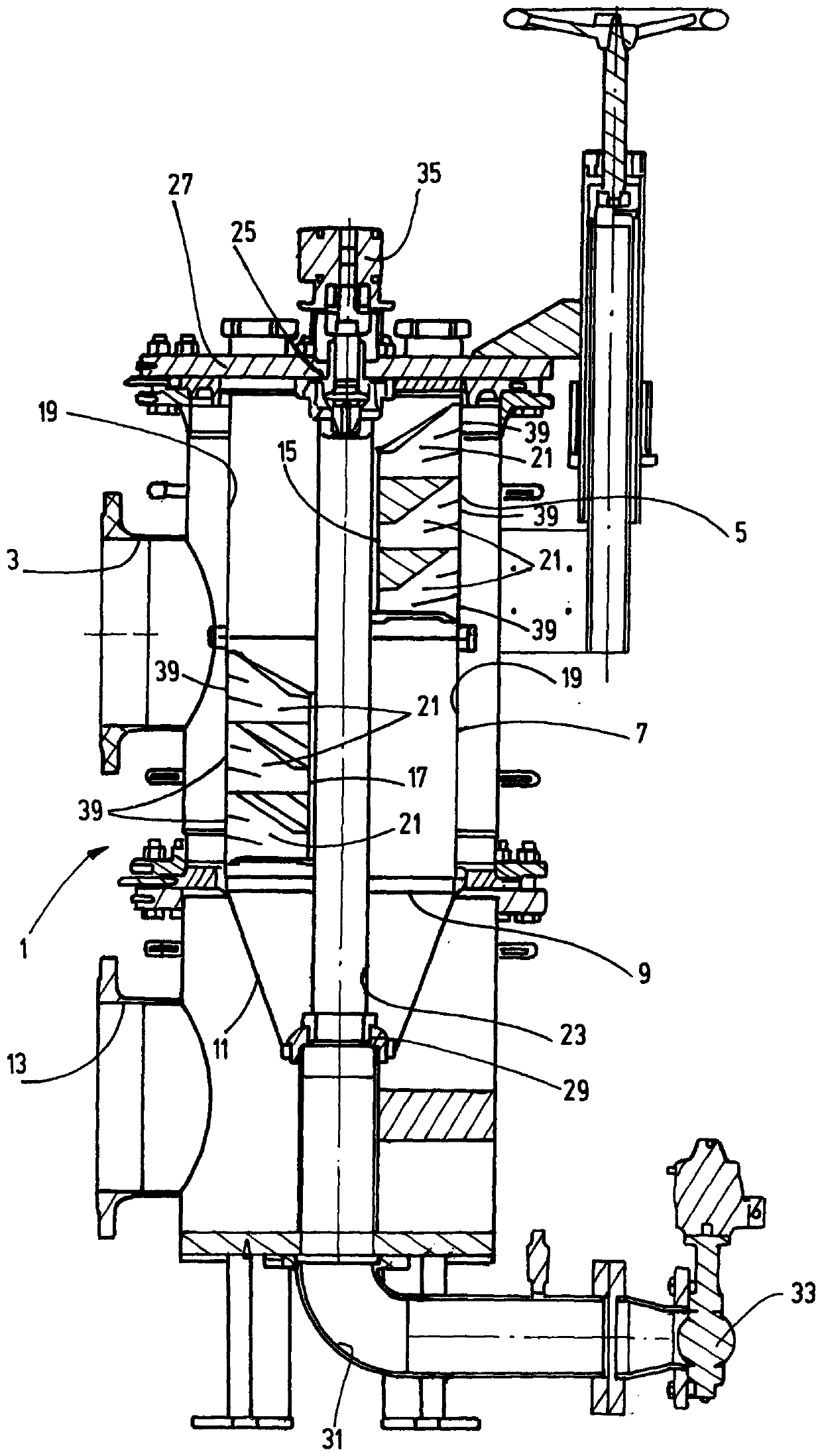
[0047] exist figure 1 An exemplary embodiment of a filter device according to the invention is shown in , wherein the filter housing as a whole is marked with 1 . A fluid outlet 3 for the filtrate is arranged laterally on the cylindrical filter housing 1 . An upper filter insert 5 and a lower filter insert 7 are accommodated in a superimposed arrangement in the filter housing 1 , through which filter inserts can flow through from the inside to the outside during the filtration process, wherein unfiltrate can be supplied to both filter inserts from the lower inlet side 9 5 and 7. Connected upstream of the inlet side 9 is an inlet filter 11 as a prefilter, through which unfiltrate can be conveyed through an inlet 13 for unfiltrate. In nautical applications, the input filter 11 is arranged as a so-called fish screen.

[0048] In order to clean deposits on the filter material 19 of the upper filter element 5 and the lower filter element 7 during backwashing, a backwashing arm 1...


PUM


Abstract

A filter device having a filter housing (1) with a fluid inlet (13) for raw fluid and with a fluid outlet (3) for filtrate and with at least one one-piece or multi-piece filter insert (5, 7) which isreceived in the filter housing (1) and can be cleaned using at least one back-flushing member (21) in counter-current to the filtration direction, which member can, by means of a fluid-guiding driveshaft (23) of a rotary drive (35), be moved along the inner side (19) of the respective filter insert (5, 7) and has, at its end adjacent to this inner side (19), a gap-shaped passage opening (39) thatruns parallel to the axis of rotation of the driveshaft (23) and discharges into a flow space (41; 57; 67) fluidically connected to the driveshaft (23), which space at least partially continuously narrows in the direction of the driveshaft (23) in a first plane in which the passage opening (39) lies, is characterized in that, in another second plane transverse to the first plane, the flow space (41; 57; 67) at least partially continuously widens proceeding from the passage opening (39) in the direction of the driveshaft (23).

Description

technical field [0001] The invention relates to a filter device comprising a filter housing having a fluid inlet for unfiltrate and a fluid outlet for filtrate and having at least one one-piece or multi-piece filter housed in the filter housing. A one-piece filter element which can be cleaned in counterflow relative to the filtration direction by means of at least one backwashing device which can be moved on the inner side of the corresponding filter element by means of a fluid-guided drive shaft of a rotary drive and On its end adjoining the inner side, it has a slit-shaped through-opening which extends parallel to the axis of rotation of the drive shaft and opens into a flow space which is fluidically connected to the drive shaft, so that The flow space tapers at least partially continuously towards the drive shaft in a first plane in which the through opening lies. Background technique [0002] The problem-free properties of lubricating oils are important for the operati...

Claims


Application Information

Patent Timeline
Patent Type & Authority Applications(China)
IPC IPC(8): B01D29/23B01D29/68B01D29/54
CPCB01D29/54B01D29/682B01D29/688B01D2201/082B01D29/232B01D35/147B01D29/00B01D29/23B01D29/58B01D29/94B01D35/005
Inventor B·施里希特J·H·格斯特纳M·多伊奇迈尔
Owner HYDAC PROCESS TECH
Features
  • R&D
  • Intellectual Property
  • Life Sciences
  • Materials
  • Tech Scout
  • Unparalleled Data Quality
  • Higher Quality Content
  • 60% Fewer Hallucinations
Learn More