Electric component compression test platform and test method
A compression test and electrical component technology, applied in the direction of measuring electricity, measuring electrical variables, testing dielectric strength, etc., can solve problems such as insufficient dielectric strength, influence of test results, damage to test instruments, etc., to achieve convenient installation and safe test process. Reliable, uniform field strength
Active Publication Date: 2019-07-02
国网安徽省电力有限公司芜湖供电公司 +1
View PDF7 Cites 2 Cited by
- Summary
- Abstract
- Description
- Claims
- Application Information
AI Technical Summary
Problems solved by technology
[0002] The main function of the arrester is to protect various electrical equipment in the power system from overvoltage impact. When performing DC withstand voltage and leakage current tests on the arrester, since the bottom of the arrester is a stud structure, if the test is placed horizontally, the conductor end of the arrester is off the ground. Closer, insufficient distance from the ground will cause damage to the test instrument. If the test is placed upright, the tester needs to use temporary objects to support the arrester to complete the test, which is very inconvenient; the contact box is widely used in various handcart type The main function of the switchgear is insulation isolation and connection transition
Method used
View moreImage
Smart ImageViewing Examples
Examples
 PUM
 Abstract
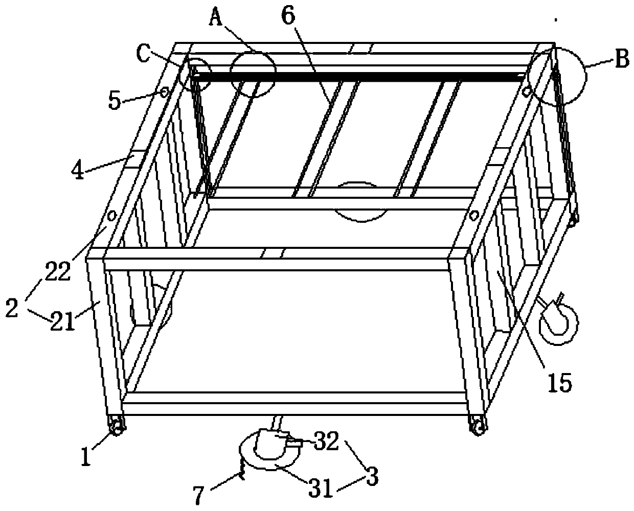
The invention relates to an electric component compression test platform comprises a frame including horizontal brackets and vertical brackets. The end portions of the horizontal brackets are fixedlyconnected with the end portions of the vertical brackets. Suspension rods are installed between the vertical brackets; chutes are formed in the suspension rods; a plurality sliding blocks are arrangedin the chutes; mounting rods are fixed at the sliding blocks; and a to-be-tested component is fixed at one end, away from the sliding block of each mounting rod. With the compression test platform, the safety risk of building a temporary bracket in the prior art is eliminated; the lightning arrester, the contact box and the bus bar bushing are mounted or dismounted conveniently and rapidly. Moreover, multiple lightning arresters, contact boxes and bus bar bushings can be installed simultaneously on one test platform, so that the test efficiency is improved; since the frame is fixed in the testing process, the installation specification of the test lead is ensured, so that the potential safety hazard is eliminated; and the internal field strength of the tested equipment is uniform, so thatthe test result is accurate and reliable.
Description
technical field [0001] The invention belongs to the technical field of electrical equipment, in particular, the invention relates to an electric component compression test platform and a test method. Background technique [0002] The main function of the arrester is to protect various electrical equipment in the power system from overvoltage impact. When performing DC withstand voltage and leakage current tests on the arrester, since the bottom of the arrester is a stud structure, if the test is placed horizontally, the conductor end of the arrester is off the ground. Closer, insufficient distance from the ground will cause damage to the test instrument. If the test is placed upright, the tester needs to use temporary objects to support the arrester to complete the test, which is very inconvenient; contact boxes are widely used in various handcart-type The main function of the switchgear is insulation isolation and connection transition. The 10KA contact boxes commonly used ...
Claims
Login to View More Application Information
Patent Timeline
 IPC IPC(8): G01R31/12G01R1/04
CPCG01R1/04G01R31/1263
Inventor 尹元亚邓帅覃启铭乔向阳仇前生赵君成李卓韩雪源潘翔王嗣常陆振坤李慧芳马兵方亮
Owner 国网安徽省电力有限公司芜湖供电公司
Features
- R&D
- Intellectual Property
- Life Sciences
- Materials
- Tech Scout
- Unparalleled Data Quality
- Higher Quality Content
- 60% Fewer Hallucinations
Learn More Browse by: Latest US Patents, China's latest patents, Technical Efficacy Thesaurus, Application Domain, Technology Topic, Popular Technical Reports.
© 2025 PatSnap. All rights reserved.Legal|Privacy policy|Modern Slavery Act Transparency Statement|Sitemap|About US| Contact US: help@patsnap.com


