

Bolt lock and key
A bolt and bolt lock technology, applied in the field of locks, can solve the problems of low key rate, low strength of lock cylinder material, and fragile lock bolt, etc., and achieve the effect of high key quantity, firm locking method and enhanced prying resistance
- Summary
- Abstract
- Description
- Claims
- Application Information
AI Technical Summary
Problems solved by technology
Method used
Image

Examples
Embodiment 1
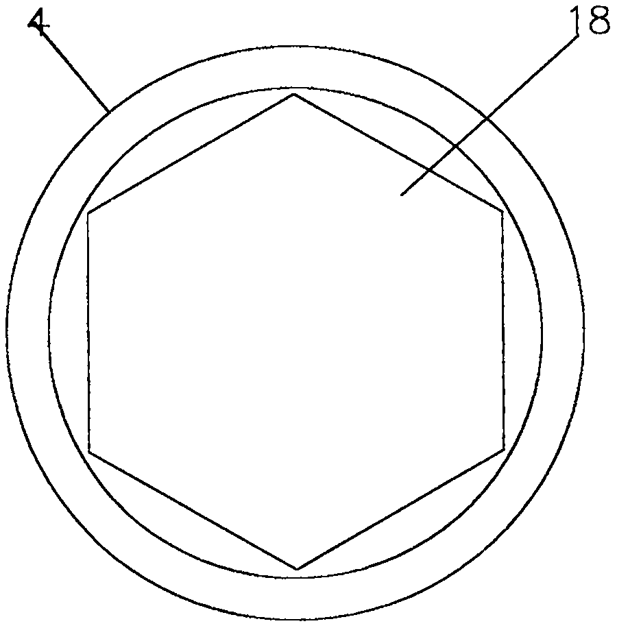
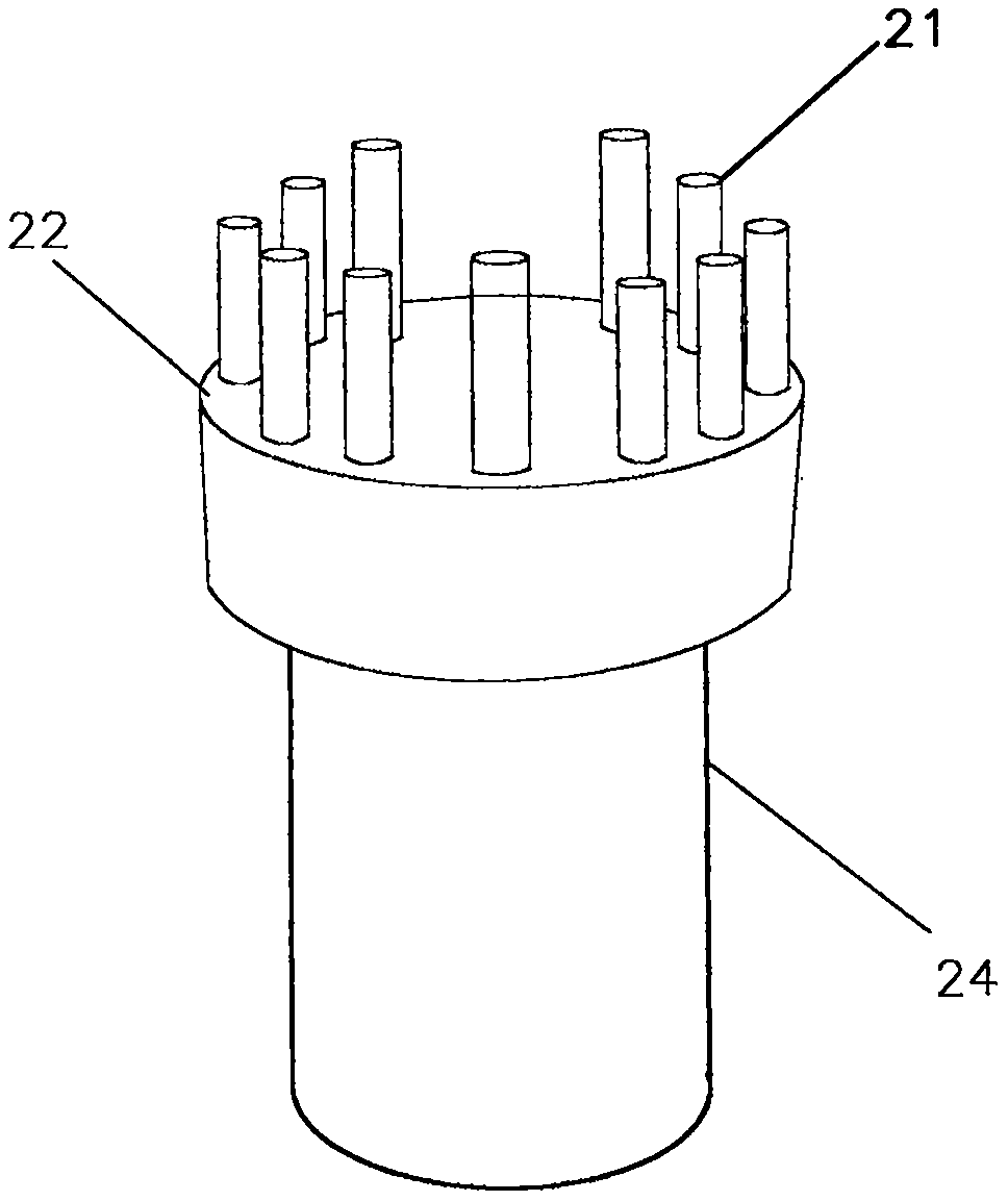
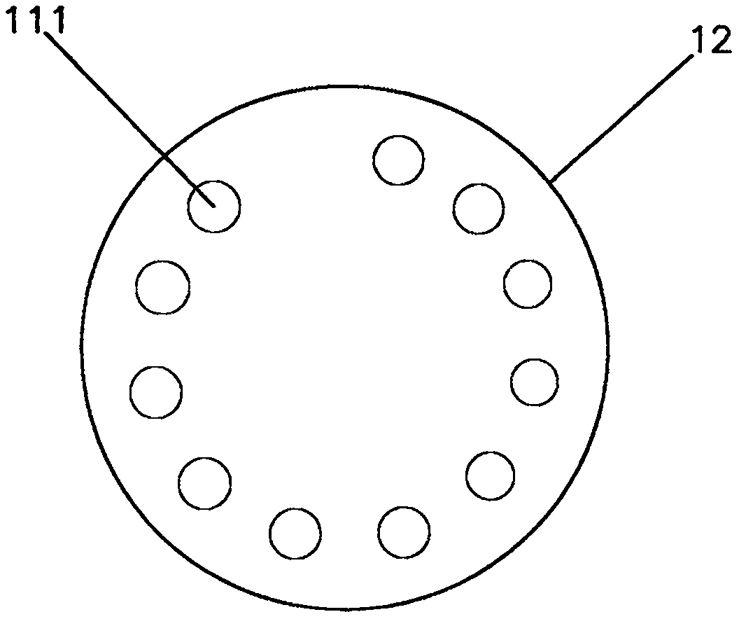
[0036] Embodiment 1, as figure 1 , figure 2 , image 3 , Figure 4 and Figure 5 As shown: a U-shaped padlock, which is composed of a bolt lock cylinder 1, a lock tube 4 and a U-shaped lock beam 5, wherein the bolt lock cylinder 1 includes a lock code screen 12, a bolt screen 13, a screw shaft 3, and a thimble 10 , code lock 11, plug 14 and spring 15, the rear end face of code lock screen 12 and the front face of plug screen 13 are closely attached to each other, and code lock screen 12 has a circle of 11 according to the arrangement mode of 30 degree indexing method The front is thin and the back is thick, and the axially arranged lock code holes 111 through which the two ends are connected. The front is thin and the back is thick is to prevent the lock code 11 from coming out of the lock code screen 12. These lock code holes 111 are equipped with locks of various code numbers. Code 11 and thimble 10, lock code 11 is cylindrical, and the cylinder of different length repr...
Embodiment 2
[0040] Embodiment 2, as figure 1 , figure 2 , image 3 , Figure 6 and Figure 7 Shown: a drawer lock, set on the side of the drawer, composed of a bolt lock core 1, a lock tube 4 and a screw tube 6, wherein the bolt lock core 1 includes a lock code screen 12, a bolt screen 13, and a screw shaft 3 , thimble 10, lock code 11, embolus 14 and spring 15, the rear end face of lock code screen 12 and the front end face of embolus screen 13, closely stick to each other, lock code screen 12 has a There are 5 rings, which are thin at the front and thick at the back, and the lock code holes 111 are arranged in the axial direction through the two ends. No. lock code 11 and thimble 10, the lock code 11 is cylindrical, and the cylinders of different lengths represent the lock code 11 of different code numbers. The thimbles 10 are pin-shaped and distributed in front of the lock hole 111. The material of the thimble 10 is stainless steel with good hardness, which is used to prevent ele...
Embodiment 3
[0044] Embodiment 3, as figure 1 , figure 2 , image 3 , Figure 8 and Figure 9 Shown: a cabinet door slider lock, which is arranged on the front of the cabinet door and consists of a bolt lock core 1, a lock tube 4 and a screw tube 6, wherein the bolt lock core 1 includes a lock code screen 12, a plug screen 13, Screw shaft 3, thimble 10, code lock 11, emboli 14 and spring 15, the rear end face of code lock screen 12 and the front end face of emboli screen 13 are closely attached to each other, and code lock screen 12 is in accordance with the 40-degree indexing method. Arrangement mode has a circle of 8 front thin and rear thick, and the lock code hole 111 that two ends are connected axially is arranged, and the front thin rear thick is in order to prevent the lock code 11 from deviating from the lock code screen 12, and these lock code holes 111 are installed There are lock codes 11 and thimbles 10 of various code numbers, and the lock code 11 is cylindrical, and cyli...
PUM
 Abstract
Description
Claims
Application Information