Array substrate and display panel

A technology of array substrate and column direction, which is applied in the direction of static indicators, identification devices, instruments, etc., to achieve the effect of improving graininess and color distortion

Active Publication Date: 2021-07-27
BEIHAI HKC OPTOELECTRONICS TECH CO LTD +1
View PDF8 Cites 0 Cited by
  • Summary
  • Abstract
  • Description
  • Claims
  • Application Information

AI Technical Summary

Problems solved by technology

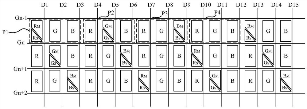
[0005] Based on this, it is necessary to provide an array substrate and a display device for the grainy display problem caused by dividing the entire row of pixels into main pixels and sub-pixels in LCS technology.

Method used


Image

  • Array substrate and display panel
  • Array substrate and display panel
  • Array substrate and display panel

Examples


Embodiment Construction

[0040] In order to facilitate the understanding of the present application, the present application will be described more fully below with reference to the relevant drawings. Preferred embodiments of the application are shown in the accompanying drawings. However, the present application can be embodied in many different forms and is not limited to the embodiments described herein. On the contrary, the purpose of providing these embodiments is to make the disclosure of the application more thorough and comprehensive.

[0041] It should be noted that when an element is referred to as being “fixed” to another element, it can be directly on the other element or there can also be an intervening element. When an element is referred to as being "connected to" another element, it can be directly connected to the other element or intervening elements may also be present. The terms "vertical," "horizontal," "left," "right," and similar expressions are used herein for purposes of ill...


PUM


Abstract

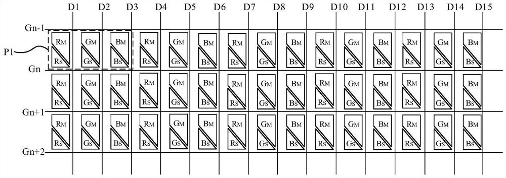
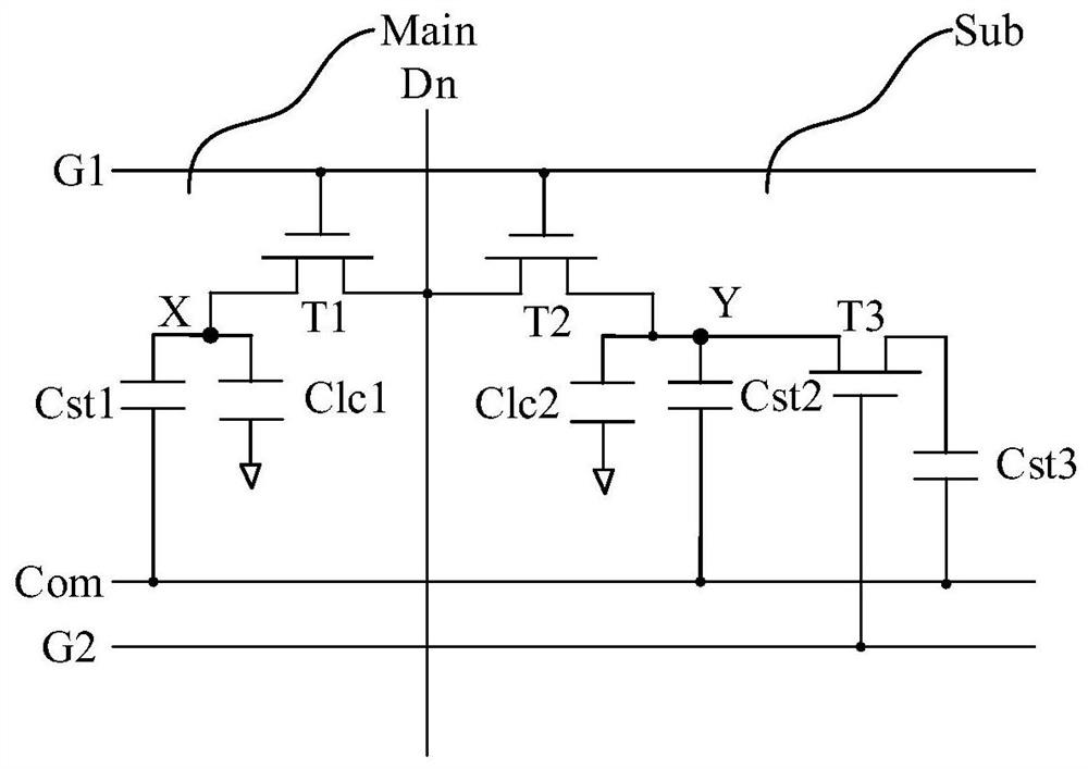
The present application relates to an array substrate and a display panel. The pixel area of ​​the array substrate is provided with a plurality of pixel units arranged in a periodic array along the column direction and the row direction; in the column direction, the sub-pixels in each column have the same color, with at least three rows of pixel units as a period, three A row of pixel units is defined as the first row of pixel units, the second row of pixel units, and the third row of pixel units. Each row of pixel units is divided into multiple pixel periods, and each pixel period includes four pixel units. Each pixel period There are three pixel units in the divided pixel unit; wherein, there is a sub-pixel in the divided pixel unit that is divided into a main pixel and a sub-pixel, and the colors of the divided sub-pixels in the same period are different; the first row The color of the divided sub-pixels in the same column of pixel units of the pixel unit, the pixel unit of the second row and the pixel unit of the third row are different. The present application can effectively improve the problem of graininess in picture display.

Description

technical field [0001] The present application relates to the field of display technology, in particular to an array substrate and a display panel. Background technique [0002] With the development of display technology, display devices are widely used due to their advantages of high image quality, power saving, thin body, and large viewing angle. Among them, large viewing angle is one of the most important factors affecting consumer experience. At present, the FFS (Fringe Field Switching, wide viewing angle technology) mode is mainly used to enlarge the viewing angle of the display device, but in this mode, since the birefringence of liquid crystal molecules will have relatively large differences in various directions, when When the orientation of the liquid crystal molecules is different, different degrees of color distortion will appear on the display screen when viewed from different viewing angles. [0003] In order to solve the color distortion under large viewing an...

Claims


Application Information

Patent Timeline
Patent Type & Authority Patents(China)
IPC IPC(8): G02F1/1362G02F1/1343G09G3/36G09G3/3225G09G3/32H01L27/32G09F9/33
CPCG02F1/1362G02F1/134309G09G3/3607G09G3/3225G09G3/32G09F9/33H10K59/121
Inventor 陈伟
Owner BEIHAI HKC OPTOELECTRONICS TECH CO LTD
Why Eureka
Try Eureka