Dither mask generation method and device

a mask and mask technology, applied in the field of dither mask generation methods and devices, can solve the problems of poor dispersion of dots, deterioration of distorted distribution of dots, etc., and achieve the effect of improving the graininess of dot arrangement and effectively suppressing banding

Active Publication Date: 2016-06-16
FUJIFILM CORP
View PDF2 Cites 7 Cited by
  • Summary
  • Abstract
  • Description
  • Claims
  • Application Information

AI Technical Summary

Benefits of technology

[0039]According to the present invention, it is possible to generate a dither mask that can improve graininess of dot arrangement of a dot density corresponding to a nozzle ejection rate compared to a conventional method, and can obtain halftone images of the dot arrangement to be a target nozzle ejection rate regardless of a recording duty. By performing halftone processing using the dither mask obtained by the present invention, banding can be effectively suppressed.

Problems solved by technology

However, in the method of generating a dither mask disclosed in Japanese Patent Application Laid-Open No. 2010-162770 gazette, since generation of dots is suppressed for predetermined specific pixels, as a result, dots are densely generated at the pixels around the specific pixels, and a dot distribution is distorted.
That is, dispersibility of dots is poor, and graininess of dot arrangement is deteriorated.
Further, in the case that the specific pixels are sparsely distributed within an area of an image to be recorded on a recording medium, at a low recording duty, an effect of suppressing the nozzle ejection rate of the nozzle group corresponding to the specific pixels cannot be obtained.
The above-described problem is related not only to the serial type inkjet printer but also to a single path type inkjet printer that uses a line head.

Method used


Image

  • Dither mask generation method and device
  • Dither mask generation method and device
  • Dither mask generation method and device

Examples


second embodiment

Modification 5 of Second Embodiment

[0324]For a definition of the input reflecting low-pass dot arrangement image, the case of defining it by “difference” by the subtraction like the expression (9) and the expression (11) and the case of defining it by “quotient” by the division like the expression (10) and the expression (12) are described, however, the subtraction can be also handled as addition of a negative value and the division can be handled as multiplication of a fraction. Therefore, under such equivalent handling, the difference by the subtraction can be noted as “sum” by the addition, and the quotient by the division can be noted as “product” by the multiplication.

[0325]

[0326]In the first embodiment and the second embodiment described above, the case that there is only one nozzle ejection rate to be reflected in the generation of the dither mask respectively for the individual pixels of the dither mask is described. However, the case that there are the plurality of nozzle e...

third embodiment

[0363]The third embodiment is a form of coping with the mask shifting processing for the example described in the first embodiment.

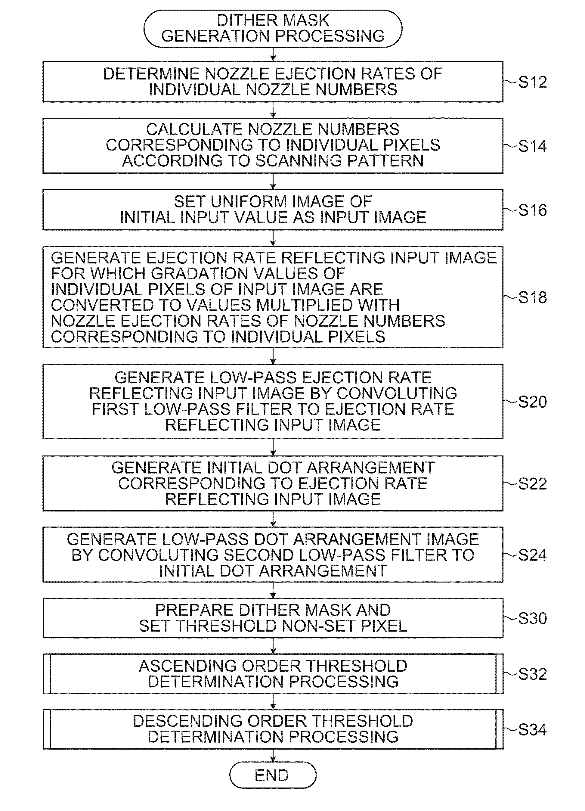
[0364]FIG. 35 is a flowchart illustrating the dither mask generation method relating to the third embodiment. In FIG. 35, the same step numbers are attached to the processes same as or similar to that in the flowchart described in FIG. 9, and the description is omitted.

[0365]In FIG. 35, instead of step S14 in FIG. 9, a process of step S14A is adopted, and a process of step S15 is added further. Also, in FIG. 35, instead of the individual processes of steps S18, S20 and S24 in FIG. 9, processes of steps S18A, S20A and S24A are adopted.

[0366]In step S14A in FIG. 35, according to the scanning pattern and the shift setting condition of the dither mask, the nozzle numbers corresponding to the individual pixels of the dither mask are calculated at individual main scanning positions of the dither mask. Provided that, “individual main scanning positions” here me...

fourth embodiment

[0376]The fourth embodiment is a form of coping with the mask shifting processing for the example described in the second embodiment.

[0377]The dither mask generation method relating to the fourth embodiment is achieved by a combination of the flowchart illustrated in FIG. 35 and the flowchart of the second embodiment described in FIG. 22.

[0378]However, in step S106 of FIG. 22, the low-pass dot arrangement image is updated in the state of shifting the dot arrangement by the mask shift amount and arranging it. Since content of the other processes is already described, the description is omitted.

[0379]As described using FIG. 27 to FIG. 36, even in the case that the dither mask is shifted in the sub scanning direction and arranged, and there are the plurality of nozzle numbers corresponding to the individual pixels of the dither mask, the dither mask that can averagely control the nozzle ejection rate can be generated.

[0380]Without being limited to the case of shifting and arranging the...


PUM


Abstract

The dither mask generation method includes: a nozzle ejection rate determination process of determining a nozzle ejection rate of each nozzle in a recording head; a corresponding nozzle specifying process of specifying the nozzle corresponding to individual pixels of a dither mask by making at least one nozzle in charge of recording at each pixel position correspond to the individual pixels of the dither mask; a nozzle ejection rate reflecting processing process of performing processing of reflecting the nozzle ejection rate on an evaluation index when individual thresholds of the dither mask are set; and a threshold setting process of setting the thresholds to the individual pixels of the dither mask on the basis of the evaluation index.

Description

CROSS-REFERENCE TO RELATED APPLICATIONS[0001]The patent application claims priority under 35 U.S.C. §119 to Japanese Patent Application No. 2014-250292 filed on Dec. 10, 2014. Each of the above application is hereby expressly incorporated by reference, in its entirety, into the present application.BACKGROUND OF THE INVENTION[0002]1. Field of the Invention[0003]The present invention relates to a dither mask generation method and device, and in particular relates to a technology of generating a dither mask used in halftone processing utilized in ink ejection control of an inkjet printer.[0004]2. Description of the Related Art[0005]Japanese Patent Application Laid-Open No. 2010-162770 gazette discloses a serial type inkjet printer that controls ejection of each nozzle of a print head by performing halftone processing by an ordered dither method using a dither mask. The serial type inkjet printer records images on a recording medium by repeating a scan operation of ejecting ink from a n...

Claims


Application Information

Patent Timeline
Patent Type & Authority Applications(United States)
IPC IPC(8): B41J2/045
CPCB41J2/04586B41J2/04558G06K15/107
Inventor KATSUYAMA, KIMITO
Owner FUJIFILM CORP
Why Eureka
Try Eureka