
Eureka
For R&D, Eureka makes reading and utilizing patents & technical documents easy.
Eureka AIR
Designed for self-driven R&D workflows. Generate viable solutions, solve complex R&D challenges, empower your innovation with AI.

Eureka Materials
Designed for material experts only. Revolutionize your material R&D, from search, analyze, to developing new materials.

TechResearch
Generate reliable direction feasibility study reports for your R&D in just a few steps.

TechSeek
Discover and master advanced knowledge NOW. Basics, ideas, possibilities, all at once.

TechMind
As an expert in R&D Theories, TechMind can generates customized viable solutions instantly.

TechRisk
Analyze your overall solution with one click, know your potential R&D risks in advance.

TechMonitor
Get weekly tech updates, stay abreast of the latest tech innovations and key insights.
Corner speed planning method and device of automatic guiding device
A technology of speed planning and automatic guidance, applied in two-dimensional position/course control, vehicle position/route/altitude control, non-electric variable control, etc., can solve the problems of poor control accuracy and high cost
- Summary
- Abstract
- Description
- Claims
- Application Information
AI Technical Summary
Problems solved by technology
Method used
Image

Examples
no. 1 example
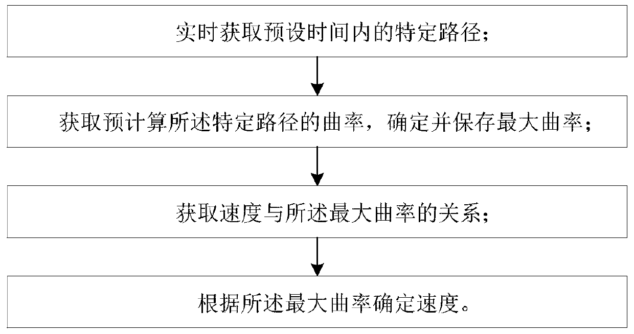
[0041] This embodiment provides a curve speed planning method for an automatic guidance device, refer to figure 1 , the curve speed planning method of the automatic guidance device includes:
[0042] Obtain a specific path within a preset time in real time;
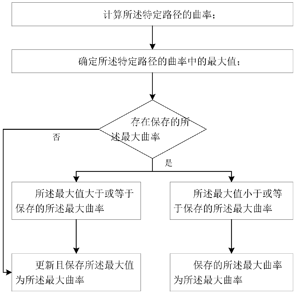
[0043] calculating the curvature of said particular path, determining and storing the maximum curvature;
[0044] obtaining the relationship between velocity and said maximum curvature;
[0045] Velocity is determined from said maximum curvature.
[0046] The automatic guidance device will obtain a walking path from the first location to the second location during the task execution from the first location to the second location, and the walking path may be static or dynamic, but no matter Whether it is a static or dynamic walking path, the automatic guiding device will obtain the subsequent walking path in advance during the process of walking along the walking path.
[0047] The preset time is a time window after th...
no. 2 example
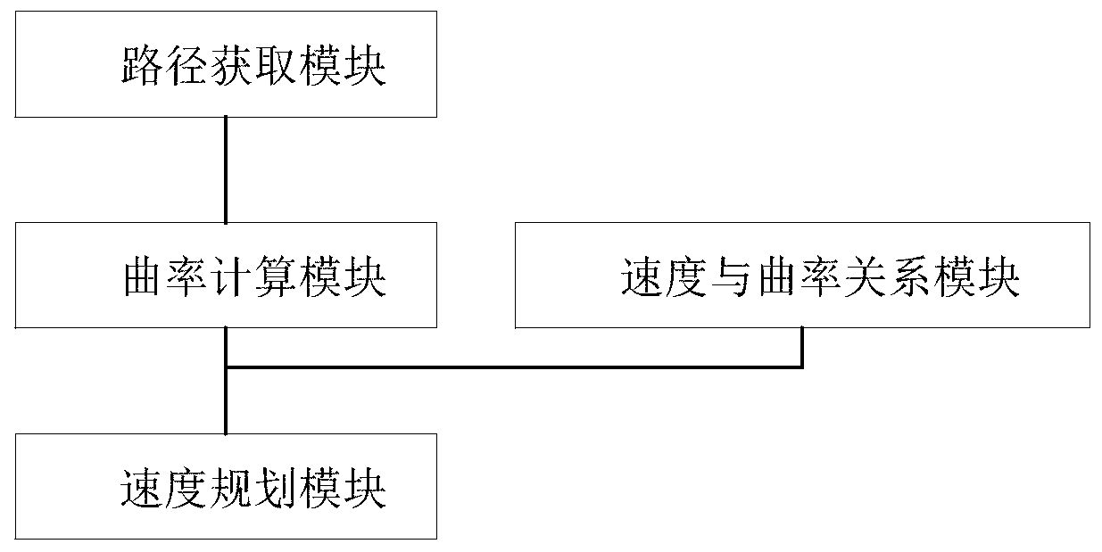
[0069] This embodiment provides a curve speed planning device for an automatic guidance device, refer to image 3 ,include:
[0070] a path acquisition module, the path acquisition module acquires the specific path within the preset time in real time;
[0071] a curvature calculation module, the curvature calculation module calculates the curvature of the specific path, and determines and saves the maximum curvature;
[0072] a velocity-curvature relationship module, the relationship between the velocity and the maximum curvature is stored in the velocity-curvature relationship module;
[0073] a velocity planning module that determines the velocity.
[0074] That is, the path acquisition module acquires the specific path within the preset time in real time, and outputs it to the curvature calculation module, and the curvature calculation module calculates the curvature of the specific path in real time, determines and saves the maximum curvature, and the The speed planning...
no. 3 example
[0077] This embodiment provides a computer-readable storage medium on which a computer program is stored, and when the computer program is executed by a processor, the curve speed of the automatic guidance device according to any one of the first embodiment is realized. planning method.
PUM
 Abstract
Description
Claims
Application Information
 - R&D Engineer
- R&D Manager
- IP Professional
- Industry Leading Data Capabilities
- Powerful AI technology
- Patent DNA Extraction
Browse by: Latest US Patents, China's latest patents, Technical Efficacy Thesaurus, Application Domain, Technology Topic, Popular Technical Reports.
© 2024 PatSnap. All rights reserved.Legal|Privacy policy|Modern Slavery Act Transparency Statement|Sitemap|About US| Contact US: help@patsnap.com