
Method for determining fault removal time of flexible direct current power grid under bipolar short circuit

A bipolar short circuit and fault removal technology, applied in circuit devices, emergency protection circuit devices, electrical components, etc., can solve the problems of system safety hazards, large fluctuations in DC bus voltage, low inertia of flexible DC power grids, etc., and reduce the operating speed. requirements, delayed action time, safety and effect of stable voltage sag margin

Active Publication Date: 2019-07-05
NORTH CHINA ELECTRIC POWER UNIV (BAODING)
View PDF7 Cites 2 Cited by
  • Summary
  • Abstract
  • Description
  • Claims
  • Application Information

AI Technical Summary

Problems solved by technology

However, the inertia of the flexible DC grid is low. After a bipolar short-circuit fault occurs, large fluctuations or continuous oscillations of the DC bus voltage will cause serious safety hazards to the system.

Method used


Image

  • Method for determining fault removal time of flexible direct current power grid under bipolar short circuit
  • Method for determining fault removal time of flexible direct current power grid under bipolar short circuit
  • Method for determining fault removal time of flexible direct current power grid under bipolar short circuit

Examples


Embodiment 1

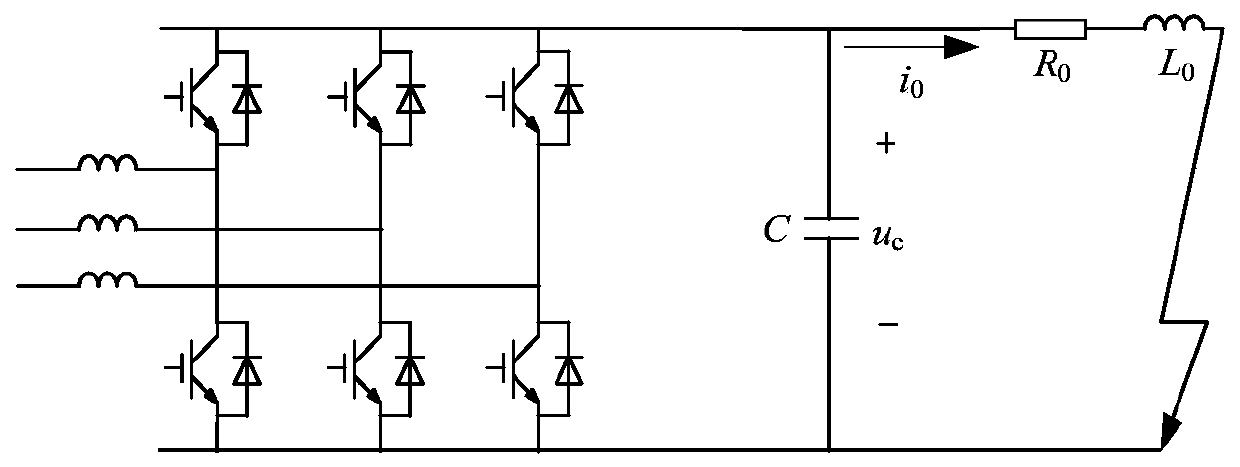
[0103] The present invention builds such as in Matlab / Simulink environment Figure 6 The simulation model of the two-terminal flexible DC grid is shown. On the power supply side, the power frequency three-phase AC power supply is filtered and transformed, and then connected to the VSC1 converter to connect to the DC power grid. The voltage at both ends of the parallel capacitor C represents the DC bus voltage. On the load side, the duty ratio of the converter VSC2 is adjusted to ensure that the connected load exhibits constant power characteristics. The basic parameters of the simulation model are shown in Table 1.

[0104] Table 1 Basic parameters of flexible DC grid

[0105]

[0106] It can be seen from Table 1 that when the system runs stably, U b =500V, I b = 40A, P 0 =20kw, line equivalent resistance R L =5.8Ω, DC side parallel capacitance C=3mF. by the formula The operating point voltage U of the system limit voltage can be obtained cmax is 340V. At the sam...

Embodiment 2

[0115] After the flexible DC grid runs stably, the bipolar short-circuit fault of the system is simulated through the simulation model. At the initial moment, the system runs stably at 498V with a 20kw constant power load. After 0.02s, a bipolar short-circuit fault occurs, the capacitor discharges, and the bus voltage drops. When the fault is removed at different times, the response result of the system is as follows: Figure 9 shown.

[0116] When a bipolar short-circuit fault occurs, at four different times (t a = 0.025s, t b = 0.028s, t c = 0.03s and t d =0.031s) to remove the fault, the response result is as follows Figure 9 shown. at t a , t b and t c The short-circuit fault is cut off at all times, and the DC bus voltage drops to 470V, 375V and 342V respectively. With the recovery of the fault, the system in the first two working conditions resumes stable operation, the system in the third working condition runs stably at 360V, and the system in the fourth work...

Embodiment 3

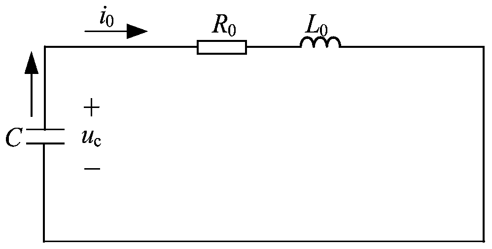
[0118] system at different fault parameters R 0 , L 0 Under , the simulation changes of DC bus voltage and fault removal time are as follows: Figure 10 shown.

[0119] With the system equivalent failure parameter R 0 , L 0 change, the fault removal time t 1x The simulated values ​​are shown in Table 3.

[0120] Table 3 Simulation values ​​of fault removal time under different parameters

[0121]

[0122] For the flexible DC grid with given fault parameters, the fault removal time t obtained by simulation is 1x Compared with the theoretically calculated values ​​(shown in Table 2), the error results are shown in Table 4.

[0123] Table 4 Error value of fault removal time under different parameters

[0124]

[0125] It can be seen from Table 4 that under the four different fault parameters, as the fault removal time prolongs, the error percentage between the theoretical and simulation values ​​of the system gradually decreases, and the accuracy of the theoretical ...


PUM


Abstract

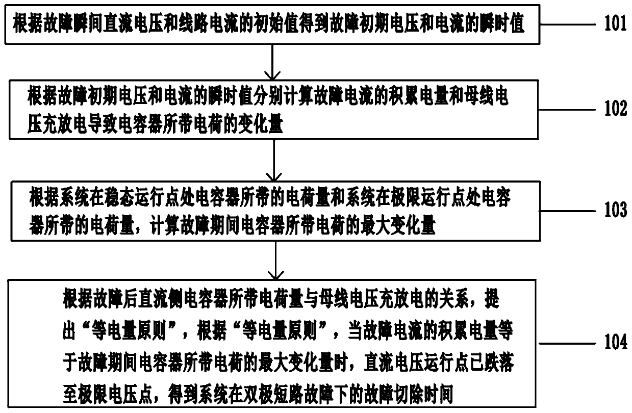
The invention discloses a method for determining fault removal time of a flexible direct current power grid under a bipolar short circuit. The method comprises the steps that the voltage and current instantaneous values at the fault initial period can be obtained according to fault instantaneous direct current voltage and the initial value of the line current; the accumulated electric quantity ofthe fault current and the change amount of the electric charges of a capacitor caused by the charging and discharging of a bus voltage are calculated according to the voltage and current instantaneousvalues at the fault initial period; according to the amount of electric charges carried by the capacitor at the steady-state operating point and the electric charge amount of the capacitor at the limit operating point of the system, the maximum change quantity of electric charges carried by the capacitor is calculated during the fault period; according to a principle of equal electric quantity, when the accumulated electric quantity of the fault current is equal to the maximum change amount of the electric charges of the capacitor during the fault period, the fault removal time of the systemunder the bipolar short circuit fault is obtained. According to the method for determining the fault removal time of the flexible direct current power grid under the bipolar short circuit, the operation requirements of the direct current system on the circuit breaker can be reduced, and the transient stability of the system can be enhanced.

Description

technical field [0001] The invention relates to the technical field of fault analysis and protection of a flexible DC power grid, in particular to a method for determining the fault removal time of a flexible DC power grid under a bipolar short circuit. Background technique [0002] With the widespread application of distributed energy and constant power loads, the flexible DC grid has become the focus of research and application at home and abroad relying on its advantages. Compared with the AC distribution network, the flexible DC grid has the advantages of simple conversion device and low cost, and there is no need to pay attention to the impact of frequency mutation and power angle swing on power quality. At present, the measures to improve the voltage stability of the flexible DC grid include adding controllers, and analyzing the fault characteristics of the system and quickly and effectively isolating faults. However, the inertia of the flexible DC grid is low. After ...

Claims


Application Information

Patent Timeline
Patent Type & Authority Applications(China)
IPC IPC(8): H02H3/00H02H3/087
CPCH02H3/006H02H3/087
Inventor 付媛江国文张祥宇
Owner NORTH CHINA ELECTRIC POWER UNIV (BAODING)
Learn More