
Sealing parts

A technology of sealing parts and recesses, which is applied in the direction of engine sealing, engine sealing device, engine components, etc., can solve problems such as large sliding loss, reduced engine efficiency, and reduced sealing function of side seals.

Active Publication Date: 2021-01-12
EAGLE INDS
View PDF1 Cites 0 Cited by
  • Summary
  • Abstract
  • Description
  • Claims
  • Application Information

AI Technical Summary

Problems solved by technology

Therefore, the side seal with a large contact area and sliding speed not only has a large sliding loss, but also has a large wear caused by sliding, so the sealing function of the side seal is reduced, the pressure of the rotor during compression is reduced, and the air leakage is increased. The problem of reduced engine efficiency

Method used


Image

  • Sealing parts
  • Sealing parts
  • Sealing parts

Examples


Embodiment 1

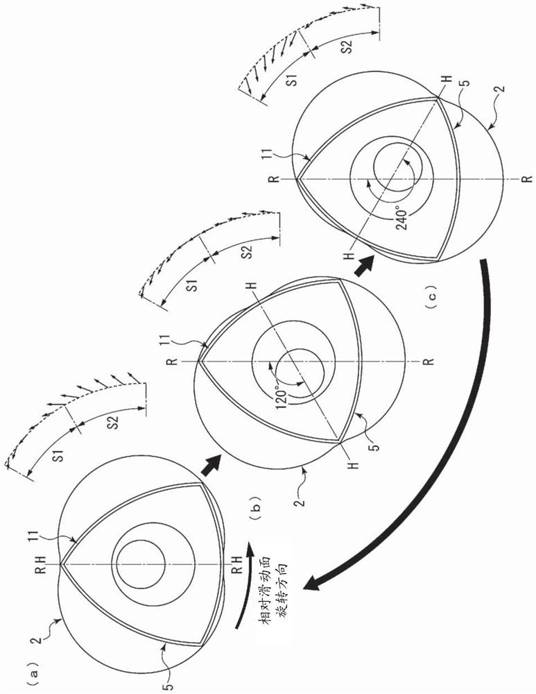
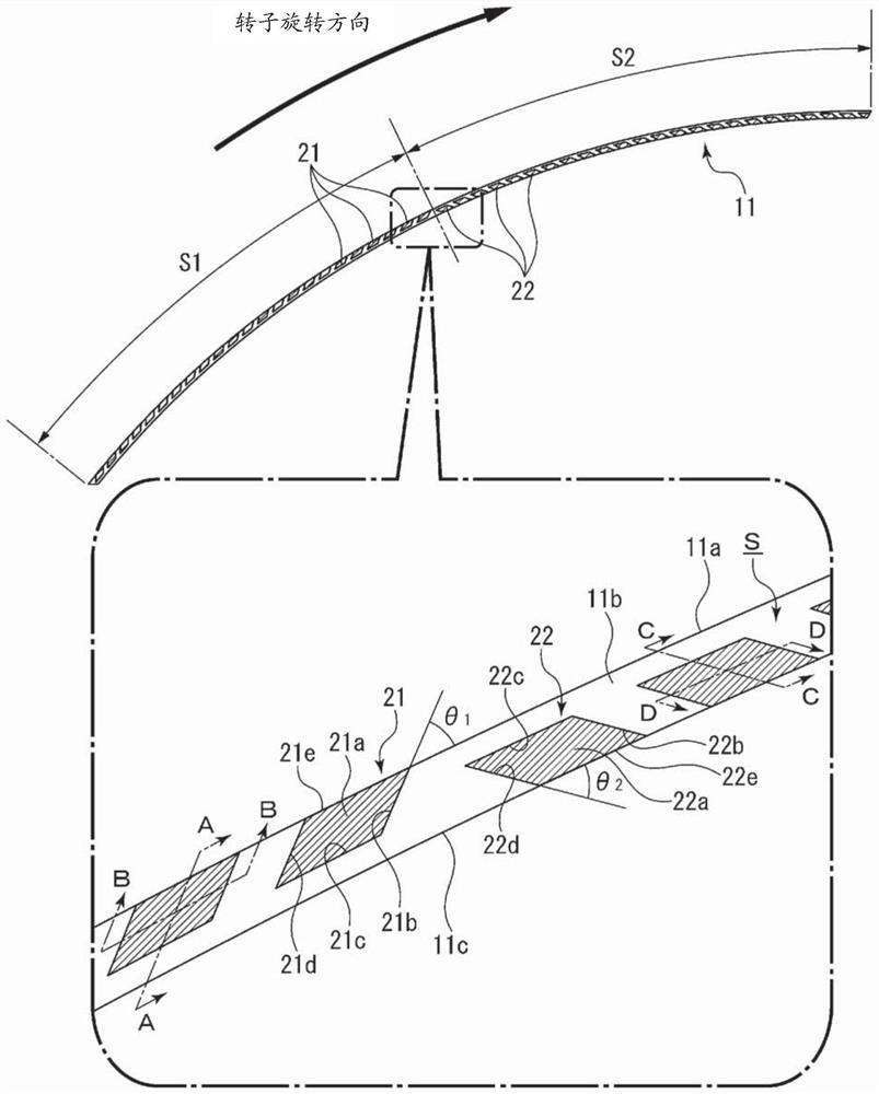
[0039] combine Figure 1 to Figure 4 , the sealing member of the present invention will be described. In addition, in this embodiment, as the sealing member of the present invention, a side seal that seals between the side surface of the rotor for a rotary engine and the side casing will be described as an example.

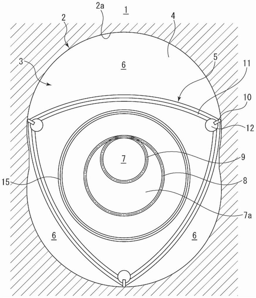
[0040] exist figure 1 Among them, the rotary engine 1 has: a casing and a rotor 5 (rotary body of the present invention), wherein the casing is clamped from both axial sides by the rotor casing 2 having the inner peripheral wall 2a of the double-arc epicycloid curve shape The rotor case 2 is composed of a pair of side cases 3 (side walls of the present invention), and the rotor 5 is accommodated in the housing chamber 4 defined by the rotor case 2 and the side cases 3 and has a triangular shape. The rotary engine 1 It also has three working chambers 6 defined by the outer peripheral wall of the rotor 5 and the inner peripheral wall 2a of a cycloidal shape.

[...

Embodiment 2

[0061] Next, combine Figure 5 , Image 6 The sealing member of Example 2 will be described. The difference between the side seal 11 of the second embodiment and the first embodiment is that the opening direction of the first lubricating mechanism and the opening direction of the second lubricating mechanism are respectively opposite to those of the first embodiment. In addition, the same code|symbol is used for the structure which overlaps with the above-mentioned embodiment, and description is abbreviate|omitted here.

[0062] The side seal 11 of the second embodiment includes: a first lubricating mechanism 31 provided at the central portion in the longitudinal direction of the side seal 11 toward the lagging side s1 in the rotational direction; In the second lubricating mechanism 32 provided on the advancing side s2 , the first lubricating mechanism 31 has an opening 31 e that opens radially inward, and the second lubricating mechanism 32 has an opening 32 e that opens ra...


PUM


Abstract

Provided is a sealing member which reduces sliding loss between a side seal provided on a side surface of a rotating body which rotates while swinging in a casing and a side casing, and improves sealing performance. A sealing member 11 is provided between the rotating body 5 that rotates while swinging and the side wall 3 of the storage room 4 in the storage room 4 divided by the casing, and has a sliding mechanism that slides relative to the side wall 3 . surface S, wherein the sliding surface S has a first lubricating mechanism 21 disposed on one side in the longitudinal direction, and a second lubricating mechanism disposed on the other side in the longitudinal direction and exerting lubricating performance for a sliding direction different from that of the first lubricating mechanism 21. Lubrication mechanism 22.

Description

technical field [0001] The present invention relates to a sealing member for sealing the side surface of a rotating body that rotates while swinging, such as a rotor for a rotary engine or a rotary compressor. Background technique [0002] In a rotary engine, a substantially triangular-shaped rotor is accommodated in a rotor housing chamber composed of a rotor case and a side case, and three working chambers are formed between the triangular-shaped rotor and the rotor case, and the rotor is positioned relative to the eccentric shaft. The eccentric is supported rotatably. In addition, the rotor is provided with a radial seal installed at each vertex of the triangular-shaped rotor and used to maintain the airtightness of the three working chambers, installed at each side of the side of the triangular-shaped rotor and used to hold the rotor and the side machine. The airtight side seals between the shells, the corner seals installed at the joints of the radial seals and the sid...

Claims


Application Information

Patent Timeline
Patent Type & Authority Patents(China)
IPC IPC(8): F01C19/08F01C1/22F01C21/04F01M1/06F02B53/00F02B55/02F16J15/16
CPCF01C1/22F01C19/08F01C21/04F01M1/06F02B53/00F02B55/02F16J15/16Y02T10/12F05D2240/55
Inventor 德永雄一郎板谷壮敏吉野显
Owner EAGLE INDS
Learn More