Display support mechanism

A technology for a support mechanism and a display, applied in the field of support frames, can solve the problem that the thickness cannot be effectively reduced, and achieve the effects of reducing materials, reducing costs, and reducing overall thickness

Pending Publication Date: 2019-07-09
DONGGUAN HONGLIAN ELECTRONICS
View PDF0 Cites 1 Cited by
  • Summary
  • Abstract
  • Description
  • Claims
  • Application Information

AI Technical Summary

Problems solved by technology

[0005] The technical problem to be solved by the present invention is to provide a display support mechanism to solve the technical problem that the thickne

Method used


Image

  • Display support mechanism
  • Display support mechanism
  • Display support mechanism

Examples


Example Embodiment

[0057] Embodiment 2

[0058] see Figure 5 , this figure is a cross-sectional view of the slide rail module in the second embodiment; the difference between this embodiment and the first embodiment is that the first extension block 3122 of the pressing block structure 312 can be formed in a manner different from that of the first embodiment. In this embodiment, the connection surface between the first extension block 3122 and the pressure block structure 312 is larger, and the first extension block 3122 can be directly formed integrally with the pressure block structure 312 .

Example Embodiment

[0059] Embodiment 3

[0060] see Image 6 and Figure 7 ,in Image 6 is the assembly drawing of the slide rail module in the third embodiment, Figure 7 It is a cross-sectional view of the slide rail module in the third embodiment; the slide rail body 311 includes at least four connecting blocks 3112, and the connecting blocks 3112 are equally divided into two rows and are arranged on the side of the base member 3111 facing the pressing block structure 312, and each row is The plurality of connecting blocks 3112 are arranged at equal intervals; the two columns of connecting blocks 3112 are respectively detachably installed with pressing block structures 312 .

[0061] Wherein, the first extension block 3122 of the pressing block structure 312 can be obtained by extending and bending as in the first embodiment, or by direct integral molding as in the second embodiment; it can be understood that the two The pressure block structure 312 and the slide rail main body 311 adopt ...

Example Embodiment

[0063] Embodiment 4

[0064] see Figure 8 , this figure is a cross-sectional view of the slide rail module in the fourth embodiment; as shown in the figure, the slide rail module 30 in this embodiment, its slider 32 also includes two second extension blocks 324, two second The extension blocks 324 are respectively connected to the two inner slides 323; the two second extension blocks 324 are formed by extending and bending the two inner slides 323 opposite to the connecting arm 322 in a direction away from the connecting arm 322, Moreover, the second extension block 324 and the inner sliding piece 323 are mutually formed with a first arc-shaped protrusion 3241 . When the sliding block 32 slides relative to the guide rail 31 , the first arc-shaped protrusion 3241 abuts against the connecting block 3112 .

[0065] Specifically, the second extension block 324 is bent toward the base member 3111, that is, the second extension block 324 is in contact with the base member 3111, an...


PUM


Abstract

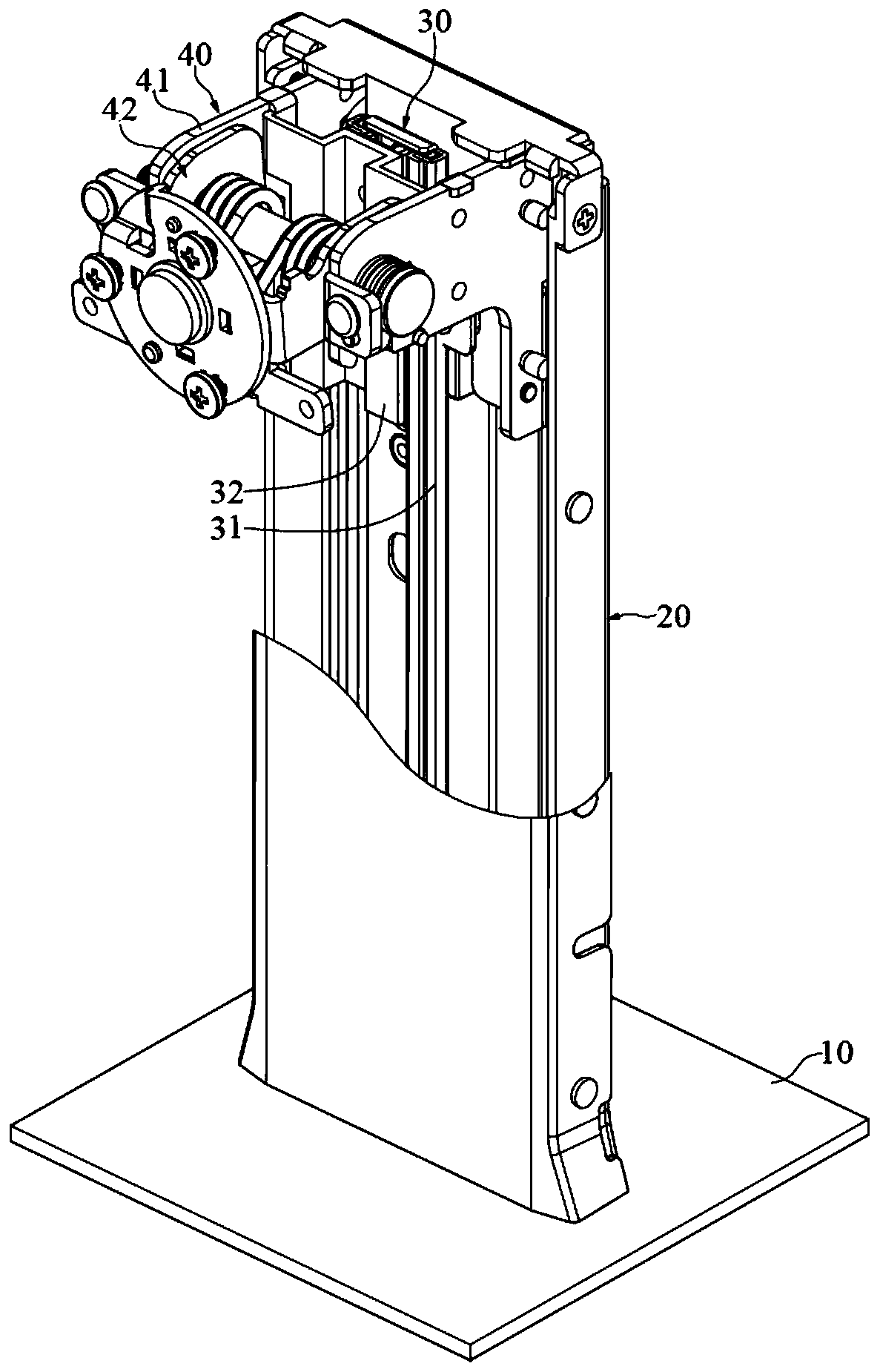
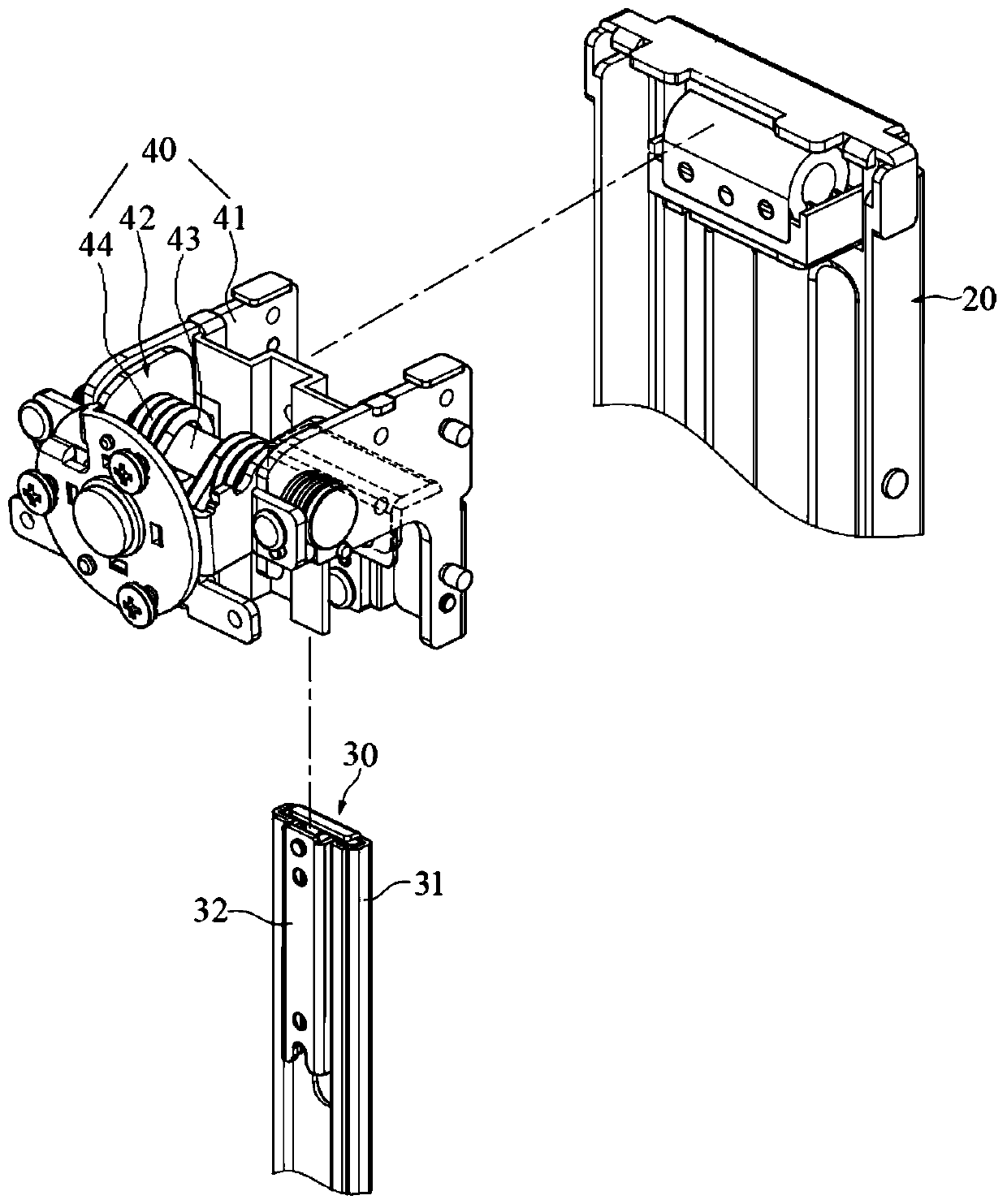
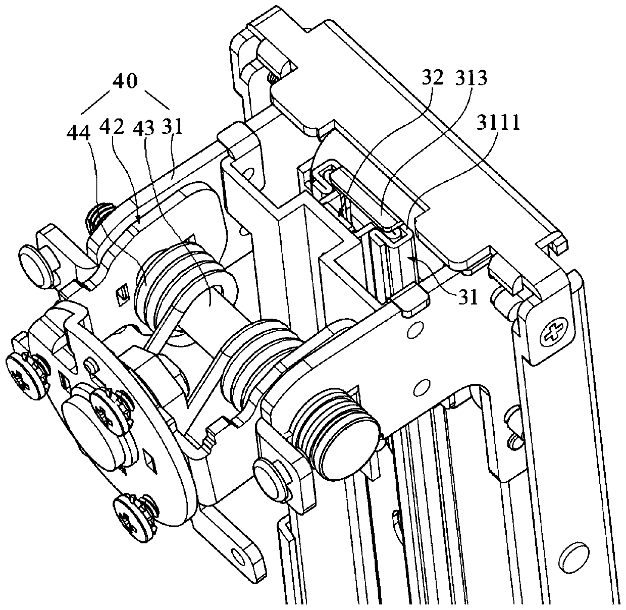
The invention discloses a display support mechanism which comprises a bottom plate and a support connected to the bottom plate. The support is connected with a slide rail module; a connecting module for connecting with a display is slidably connected onto the slide rail module; the slide rail module comprises a guide rail, and a slide block embedded with the guide rail; the guide rail comprises aslide rail body, and two pressing block structures symmetrically arranged on two opposite sides of the slide rail body; a gap for the slide block to slide is reserved between the two pressing block structures and the slide rail body; an inner slide sheet is embedded into the gap; and when the slide block slides relative to the guide rail, the inner slide sheet presses against the pressing block structures or the slide rail body of the guide rail. According to the support mechanism, the slide rail module adopts an embedded structure design, so that the slide block can realize a sliding function without the need of the assistance of a ball, the slide rail module can have the characteristic of a thin structure, the overall thickness of the support mechanism is favorably reduced, materials required for production can be reduced, and the aims of energy conservation, emission reduction, and cost reduction are achieved.

Description

technical field [0001] The invention relates to the technical field of support frames, in particular to a display support mechanism. Background technique [0002] In order to facilitate the user to adjust the height of the monitor, the general monitor support frame has a bracket and a slide rail for realizing the lifting function. The slide rail includes a linear guide rail fixed to the bracket and a slider connected to the monitor; The back and forth movement in the guide rail is mainly realized by the ball, so as to realize the up and down adjustment function of the display. [0003] It can be seen that the slide rails adopted by the existing display support frame generally have balls, and the balls are used as the slide rails of the sliding aids. Since the balls have a certain volume, a certain space must be reserved for the slide rails when designing and manufacturing. The accommodating area of ​​the balls makes the entire slide rail very thick, and the thickness of the...

Claims


Application Information

Patent Timeline
IPC IPC(8): F16M11/10F16M11/18
CPCF16M11/10F16M11/18
Inventor 郑建林张维伦张秀金
Owner DONGGUAN HONGLIAN ELECTRONICS
Why Eureka
Try Eureka