
Pumping device for seat of vehicle

A technology for pumping devices and vehicle seats, which is applied to vehicle seats, special positions of vehicles, movable seats, etc., and can solve problems such as noise and wear

Active Publication Date: 2019-07-12
HYUNDAI DYMOS
View PDF7 Cites 1 Cited by
  • Summary
  • Abstract
  • Description
  • Claims
  • Application Information

AI Technical Summary

Problems solved by technology

[0011] Here, since the lever bracket 100, the case 120, and the clutch cam 134 rotate around the same axis, and the clutch drum 132 and the brake mechanism 140 rotate around different axes, when the assembly is normally performed or the brake mechanism 140 and the case When 120 is misaligned due to external influence, the brake drum 142 rubs against the inner peripheral surface of the drum 122 of the housing 120, causing noise and wear

Method used


Image

  • Pumping device for seat of vehicle
  • Pumping device for seat of vehicle
  • Pumping device for seat of vehicle

Examples


Embodiment Construction

[0025] Hereinafter, a pumping device for a vehicle seat according to an exemplary embodiment of the present invention will be described in detail with reference to the accompanying drawings.

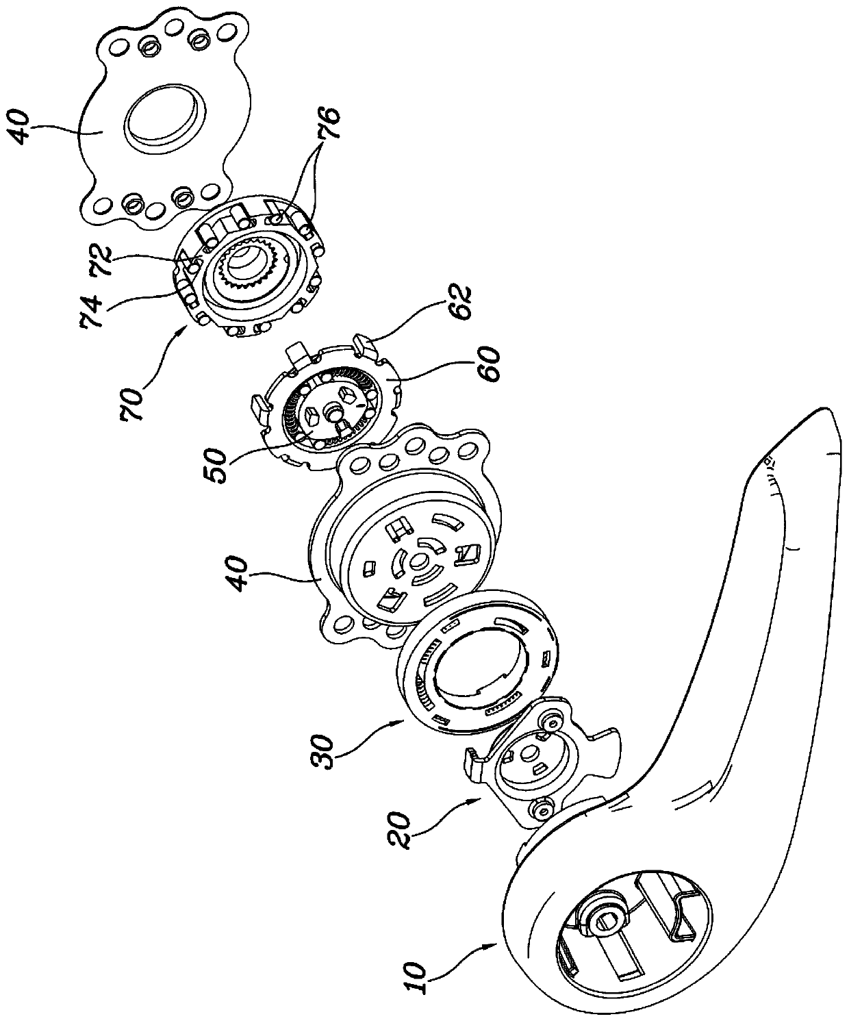
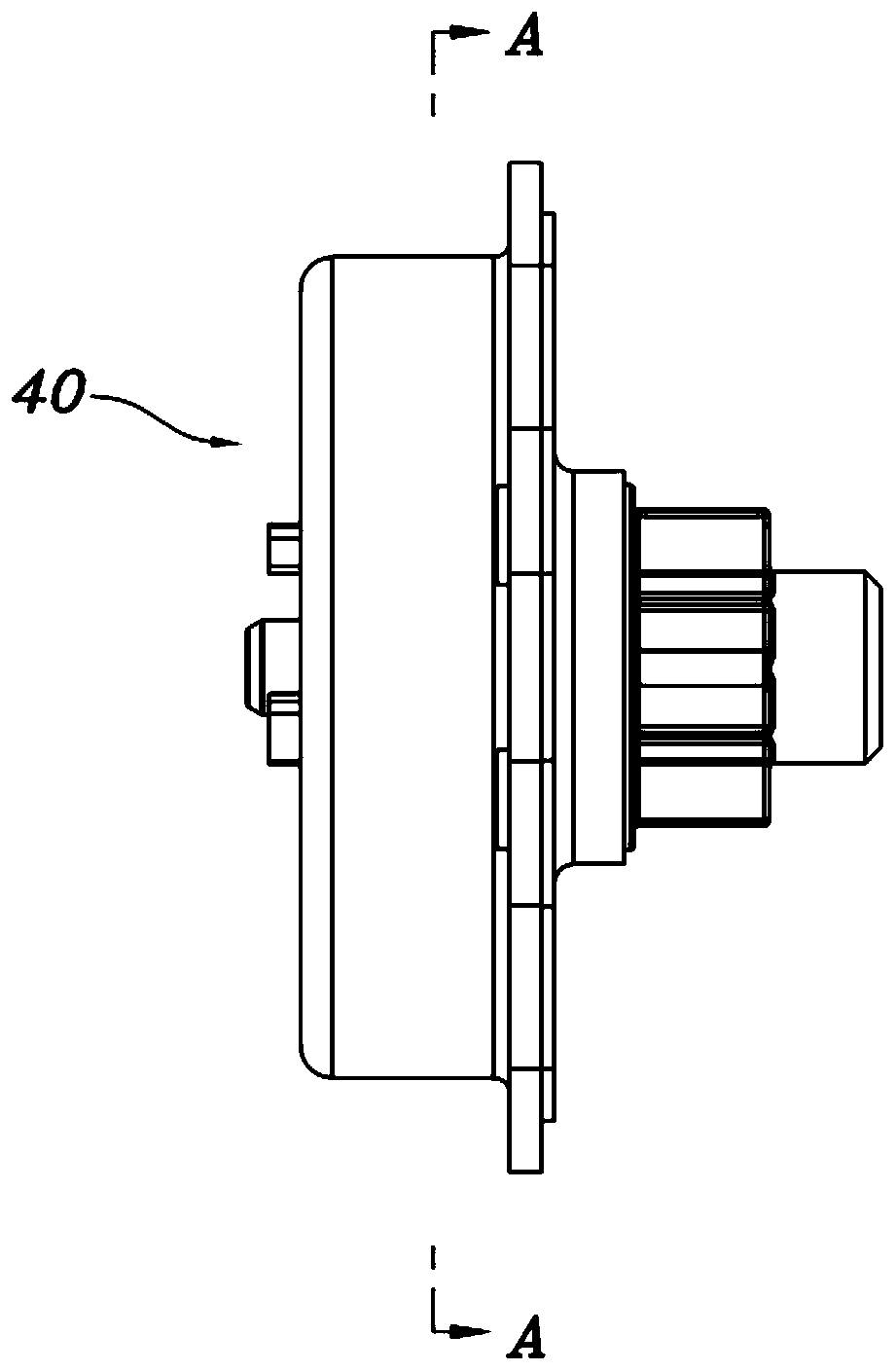
[0026] figure 2 is an exploded perspective view showing a pumping device for a vehicle seat according to an embodiment of the present invention; image 3 It is a side view showing the assembled state of the cam mechanism, the clutch mechanism and the braking mechanism of the present invention; and Figure 4 is along image 3 A cross-sectional view taken along line A-A in .

[0027] refer to Figure 2 to Figure 4 , the pumping device for a vehicle seat of the present invention includes: a cam mechanism 50 that rotates with the operating rod 10, a clutch mechanism 60 that receives power from the cam mechanism 50, and a housing 40 that accommodates the cam mechanism 50 and the clutch mechanism 60 Among them; the brake mechanism 70, which is accommodated in the housing 40 to receive pow...


PUM


Abstract

The invention provides a pumping device for a seat of a vehicle. The pumping device for the seat of the vehicle comprises: a cam mechanism rotating along with a lever; a clutch mechanism receiving power from the cam mechanism; a housing accommodating the cam mechanism and the clutch mechanism therein; a brake mechanism accommodated in the housing to receive power from the clutch mechanism, and configured such that boss portions protrude along an outer circumferential surface thereof, outer end sides of the boss portions face an inner circumferential surface of the housing, and a pressing portion protruding from the clutch mechanism is disposed between a boss portion and a neighboring boss portion; and a brake roller provided at opposite sides of each of the boss portions of the brake mechanism to be disposed between the boss portion and the pressing portion.

Description

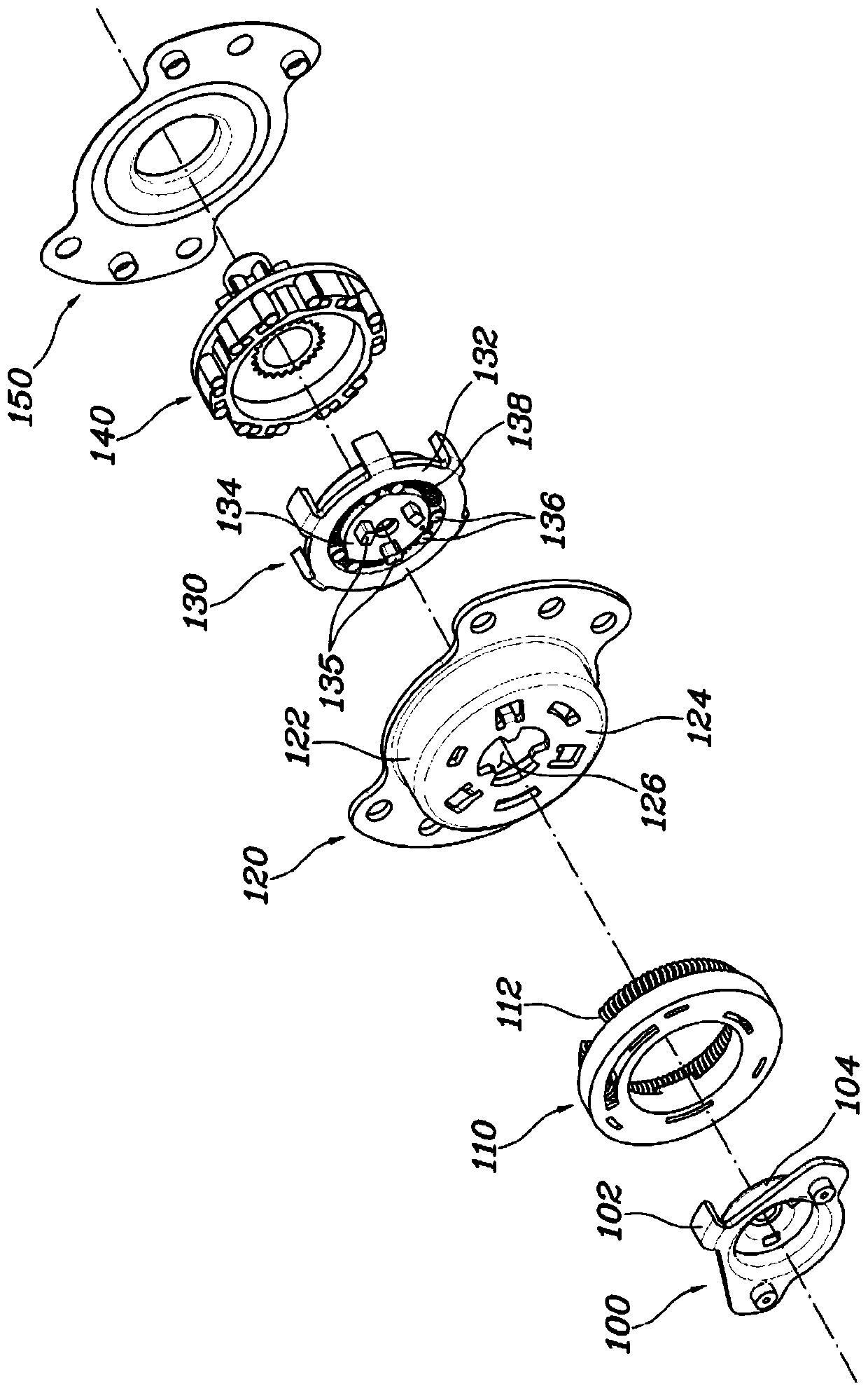
technical field [0001] The present invention relates to a pumping device for a vehicle seat that minimizes noise and wear by preventing contact of a brake mechanism with a housing. Background technique [0002] A conventional pumping device is a device that attaches to the seat and enables the seat occupant to manually adjust the height of the seat cushion to match the size of the seat occupant. [0003] If the seat occupant operates the operating lever handle installed on the side of the seat cushion clockwise or counterclockwise, the operating force of the operating lever handle is transmitted to the link mechanism through the seat pumping device to lift up according to the operating direction of the operating lever handle. Raise or lower the seat cushion to be able to adjust the height of the seat cushion. [0004] figure 1 A schematic diagram showing the components of a conventional seat pumping device. refer to figure 1 , the seat pumping device for a vehicle includ...

Claims


Application Information

Patent Timeline
IPC IPC(8): B60N2/02
CPCB60N2/02B60N2002/0204B60N2/167B60N2/168B60N2/165B60N2/1635B60N2/169
Inventor 蔡洙荣李英善
Owner HYUNDAI DYMOS
Learn More