Filling machine film coiling support frame

A support frame and filling machine technology, applied in the field of support frames, can solve problems such as troublesome operation, reel tilt affecting film, wear, etc., and achieve the effect of avoiding wear

Active Publication Date: 2019-07-12
NANJING HANERSI BIOLOGY TECHNOLOGY CO LTD
View PDF13 Cites 0 Cited by
  • Summary
  • Abstract
  • Description
  • Claims
  • Application Information

AI Technical Summary

Problems solved by technology

[0002] The membrane can be used in many places, but after the membrane is produced, in order to facilitate the movement and use of the membrane, people will roll up the membrane and then take it off for collection. Usually, people directly place the roll with the membrane on the bracket In general, due to the large amount of film, over time, it is easy to cause the reel to tilt and affect the placement of the film, and because the height of the bracket is consistent, it is easy to make the film contact with the ground and cause wear, so people will use bolts to install the reel on the On the support, and lay a protective cloth on the ground to protect the membrane, so that when the membrane needs to be used, it is necessary to twist the bolts and then remove the reel, and the operation is more troublesome

Method used


Image

  • Filling machine film coiling support frame
  • Filling machine film coiling support frame
  • Filling machine film coiling support frame

Examples


Embodiment 1

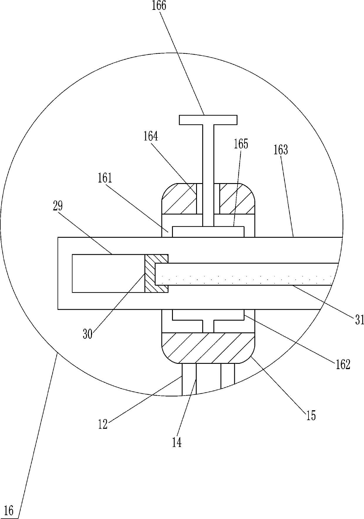
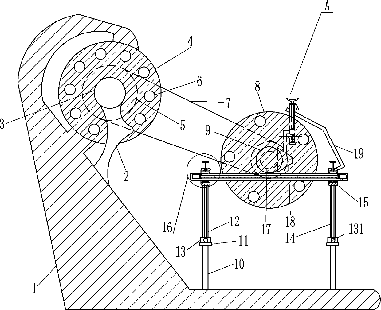
[0016] A roll film support frame of a filling machine, such as Figure 1-2 As shown, it includes a mounting seat 1, a mounting rod 2, a servo motor 3, a first film roll 4, a pulley 5, a flat belt 7, a second film roll 8, a contact block 9, a support rod 10, and a first mounting block 11. The first slide rail 12, the first sliding block 13, the fastening bolt 131, the first lifting rod 14, the second mounting block 15, and the clamping mechanism 16, the mounting seat 1 is provided with a mounting rod 2 on the upper part of the inclined surface, and the mounting rod 2 is connected to the mounting base 1 by welding, the top of the mounting rod 2 is provided with a servo motor 3, the servo motor 3 is connected to the mounting rod 2 by bolt connection, and the output shaft of the servo motor 3 is provided with a first film roll 4 A plurality of first through holes 6 are evenly spaced on the first film roll 4, four support rods 10 are symmetrically arranged on the top of the mounting ...

Embodiment 2

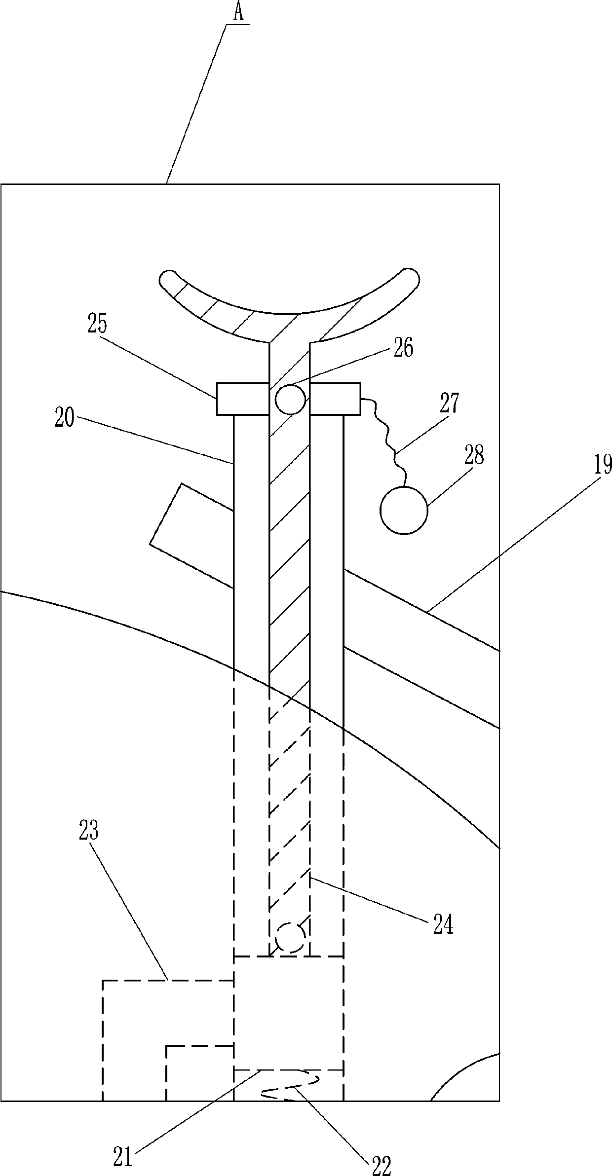
[0018] A roll film support frame of a filling machine, such as Figure 1-3 As shown, it includes a mounting seat 1, a mounting rod 2, a servo motor 3, a first film roll 4, a pulley 5, a flat belt 7, a second film roll 8, a contact block 9, a support rod 10, and a first mounting block 11. The first slide rail 12, the first sliding block 13, the fastening bolt 131, the first lifting rod 14, the second mounting block 15, and the clamping mechanism 16, the mounting seat 1 is provided with a mounting rod 2 on the upper part of the inclined surface, and the mounting rod 2 Servo motor 3 is provided on the top, the output shaft of servo motor 3 is provided with a first film roll 4, and a plurality of first through holes 6 are evenly spaced on the first film roll 4, and the top of the mounting seat 1 is symmetrical Four support rods 10 are provided, the top of the support rod 10 is provided with a first mounting block 11, the top of the first mounting block 11 is provided with a first s...

Embodiment 3

[0021] A roll film support frame of a filling machine, such as Figure 1-3 As shown, it includes a mounting seat 1, a mounting rod 2, a servo motor 3, a first film roll 4, a pulley 5, a flat belt 7, a second film roll 8, a contact block 9, a support rod 10, and a first mounting block 11. The first slide rail 12, the first sliding block 13, the fastening bolt 131, the first lifting rod 14, the second mounting block 15, and the clamping mechanism 16, the mounting seat 1 is provided with a mounting rod 2 on the upper part of the inclined surface, and the mounting rod 2 Servo motor 3 is provided on the top, the output shaft of servo motor 3 is provided with a first film roll 4, and a plurality of first through holes 6 are evenly spaced on the first film roll 4, and the top of the mounting seat 1 is symmetrical Four support rods 10 are provided, the top of the support rod 10 is provided with a first mounting block 11, the top of the first mounting block 11 is provided with a first s...


PUM


Abstract

The invention relates to a support frame, in particular to a filling machine film coiling support frame. The provided filling machine film coiling support frame achieves the technical effects that coiling blocks wound with different numbers of films can be better placed, the situation that the films are abraded due to contact with the ground is avoided, and the condition that placement of the films is affected due to the tilting phenomenon can also be avoided. According to the technical scheme, the filling machine film coiling support frame comprises a mounting base, a mounting rod, a servo motor, a first film coiling block, a belt wheel, a flat belt, a second film coiling block, a contact block, a support rod, a first mounting block and the like; the mounting rod is arranged on the upperportion of the inner inclined surface of the mounting base; the servo motor is arranged at the top of the mounting rod; and the first film coiling block is arranged on an output shaft of the servo motor. By returning the second film coiling block wound with the films on first support blocks, the first support blocks on the front and rear sides can keep the second film coiling block rotating in a horizontal state through the contact block, and the condition that placement of the films is affected due to the tilting state can be avoided.

Description

Technical field [0001] The invention relates to a support frame, in particular to a film roll support frame of a filling machine. Background technique [0002] The film can be used in many places, but after the film is produced, in order to facilitate the movement and use of the film, people will roll the film and then take it off for collection and processing. Usually, people directly place the roll of film on the holder. Because of the large amount of film and a long time, it is easy to cause the roll to tilt and affect the placement of the film, and because the height of the bracket is consistent, it is easy to make the film contact with the ground and cause abrasion, so people will install the roll on the roll by bolts. On the support, and then spread a protective cloth on the ground to protect the membrane, so when the membrane needs to be used, it is necessary to twist off the bolts and then take off the reel. The operation is more troublesome. Summary of the invention [0...

Claims


Application Information

Patent Timeline
Patent Type & Authority Applications(China)
IPC IPC(8): B65B41/12B65B59/00B65H16/02
CPCB65B41/12B65B59/00B65H16/02
Inventor 余万鹏
Owner NANJING HANERSI BIOLOGY TECHNOLOGY CO LTD
Why Eureka
Try Eureka