
A method of analyzing linear frequency modulated signal

A linear frequency modulation and signal technology, applied in special data processing applications, complex mathematical operations, instruments, etc., can solve the problems of WVD aliasing, difficulty in resampling, and difficulty in accurately extracting signal information, and achieve high time-frequency resolution. Effect

Active Publication Date: 2019-07-12
SHANGHAI INST OF MICROSYSTEM & INFORMATION TECH CHINESE ACAD OF SCI +2
View PDF3 Cites 2 Cited by
  • Summary
  • Abstract
  • Description
  • Claims
  • Application Information

AI Technical Summary

Problems solved by technology

Another scheme proposed by SARKAR B et al. (see "SARKAR B, PANIGRAHI RK, and MISHRA AK. Sidelobe Suppression in Wigner Distribution Using Non-Linear Apodization [C]. India Conference (INDICON), 2009 Annual IEEE, Gujarat, India, 2009 :1-4.doi:10.1109 / INDCON.2009.5409393) Combined with the nonlinear apodization algorithm to suppress the sidelobe of WVD, but it only analyzes the single-component LFM signal, and the cross-term under the multi-component LFM signal is not analyzed Analysis and solution
[0006] Second, the period of the signal in the frequency domain after discrete WVD will become half of the sampling rate, so even when the sampling rate is equal to the Nyquist rate, WVD will still produce aliasing
Frequency domain aliasing will cause spectral components to appear in the area where there is no signal in the time-frequency diagram of the signal, or cause other spectral components to be mixed in the area where there is a signal, which will make it difficult to accurately extract signal information.
The direct measure to deal with this problem is to increase the sampling frequency, but sometimes, once the signal is sampled, it is difficult to resample it. In addition, increasing the sampling rate will also increase the amount of computation and bring additional hardware overhead

Method used


Image

  • A method of analyzing linear frequency modulated signal
  • A method of analyzing linear frequency modulated signal
  • A method of analyzing linear frequency modulated signal

Examples


Embodiment Construction

[0031] It should be noted that components in the various figures may be shown exaggerated for the purpose of illustration and are not necessarily true to scale. In the various figures, identical or functionally identical components are assigned the same reference symbols.

[0032] In the present invention, each embodiment is only intended to illustrate the solutions of the present invention, and should not be construed as limiting.

[0033] In the present invention, unless otherwise specified, the quantifiers "a" and "an" do not exclude the scene of multiple elements.

[0034] It should also be pointed out here that in the embodiments of the present invention, for the sake of clarity and simplicity, only a part of parts or components may be shown, but those skilled in the art can understand that under the teaching of the present invention, specific The scene needs to add the required parts or components.

[0035] It should also be pointed out that within the scope of the pre...


PUM


Abstract

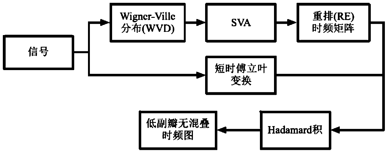
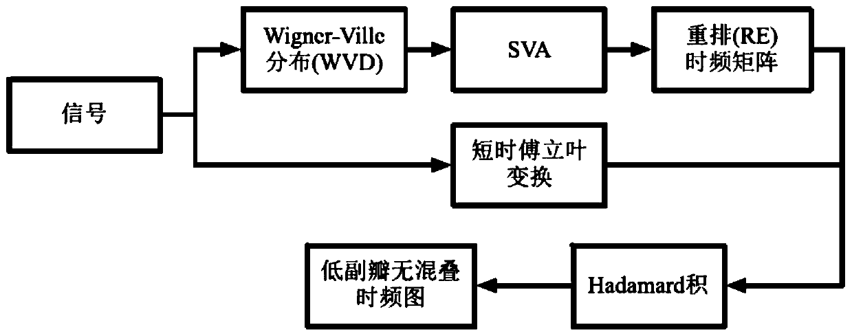
The invention relates to a method for analyzing a linear frequency modulation signal. The method comprises the following steps: carrying out Wignard WVD conversion on the linear frequency modulation signal to obtain a first signal; processing the first signal by using a spatial apodization SVA algorithm to obtain a second signal; performing time-frequency matrix rearrangement on the second signalto obtain a third signal; performing short-time Fourier transform (STFT) on the linear frequency modulation signal to obtain a fourth signal; and performing an AdammaHadamard product on the third signal and the fourth signal. According to the invention, the obtained time-frequency distribution can effectively reduce the sidelobe level and eliminate the phenomena of cross terms and spectrum aliasing at the same time.

Description

technical field [0001] The present invention generally relates to the field of time-frequency analysis in the field of signal processing, and specifically relates to a method for analyzing linear frequency modulation signals. Background technique [0002] According to the statistical characteristics such as frequency and power spectrum of the signal, it can be divided into non-stationary signal and stationary signal. According to whether the frequency of the signal changes linearly with time, the non-stationary signal can be divided into nonlinear frequency modulation signal and linear frequency modulation (Linear Frequency Modulation, LFM) signal (hereinafter also referred to as linear frequency modulation signal or LFM signal). As a spread spectrum signal with a large time-frequency band product, LFM signal is widely used in radar, communication, sonar and seismic exploration systems, and has high research value. [0003] The time-frequency analysis tools for non-stationa...

Claims


Application Information

Patent Timeline
IPC IPC(8): G06F17/14G06F17/16
CPCG06F17/141G06F17/16
Inventor 高新海郭汝江刘会杰姜在阳刘沛龙
Owner SHANGHAI INST OF MICROSYSTEM & INFORMATION TECH CHINESE ACAD OF SCI
Learn More