Mechanical adjustment conditioning type artificial limb ankle joint

A technology of mechanical adjustment and ankle joints, applied in the field of prosthetics, can solve the problems of high price of adjustable prosthetic ankle joints and unbearable for amputees, and achieve the effect of low manufacturing cost, convenient use and simple operation

Active Publication Date: 2019-07-16
湖南海弘医疗科技有限公司
View PDF1 Cites 4 Cited by
  • Summary
  • Abstract
  • Description
  • Claims
  • Application Information

AI Technical Summary

Problems solved by technology

[0005] In view of the deficiencies in the prior art, the object of the present invention is to provide a mechanically adjustable prosthetic ankle joint, which solves the problem that the existing adjustable prosthetic ankle joint is very expensive and cannot be afforded by many amputees

Method used


Image

  • Mechanical adjustment conditioning type artificial limb ankle joint
  • Mechanical adjustment conditioning type artificial limb ankle joint
  • Mechanical adjustment conditioning type artificial limb ankle joint

Examples


Embodiment

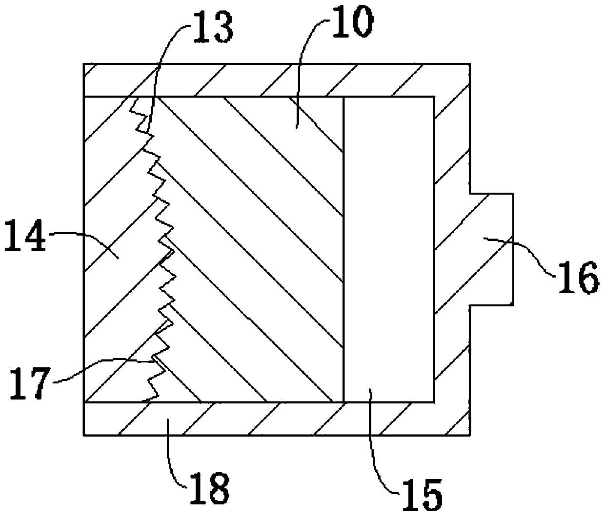
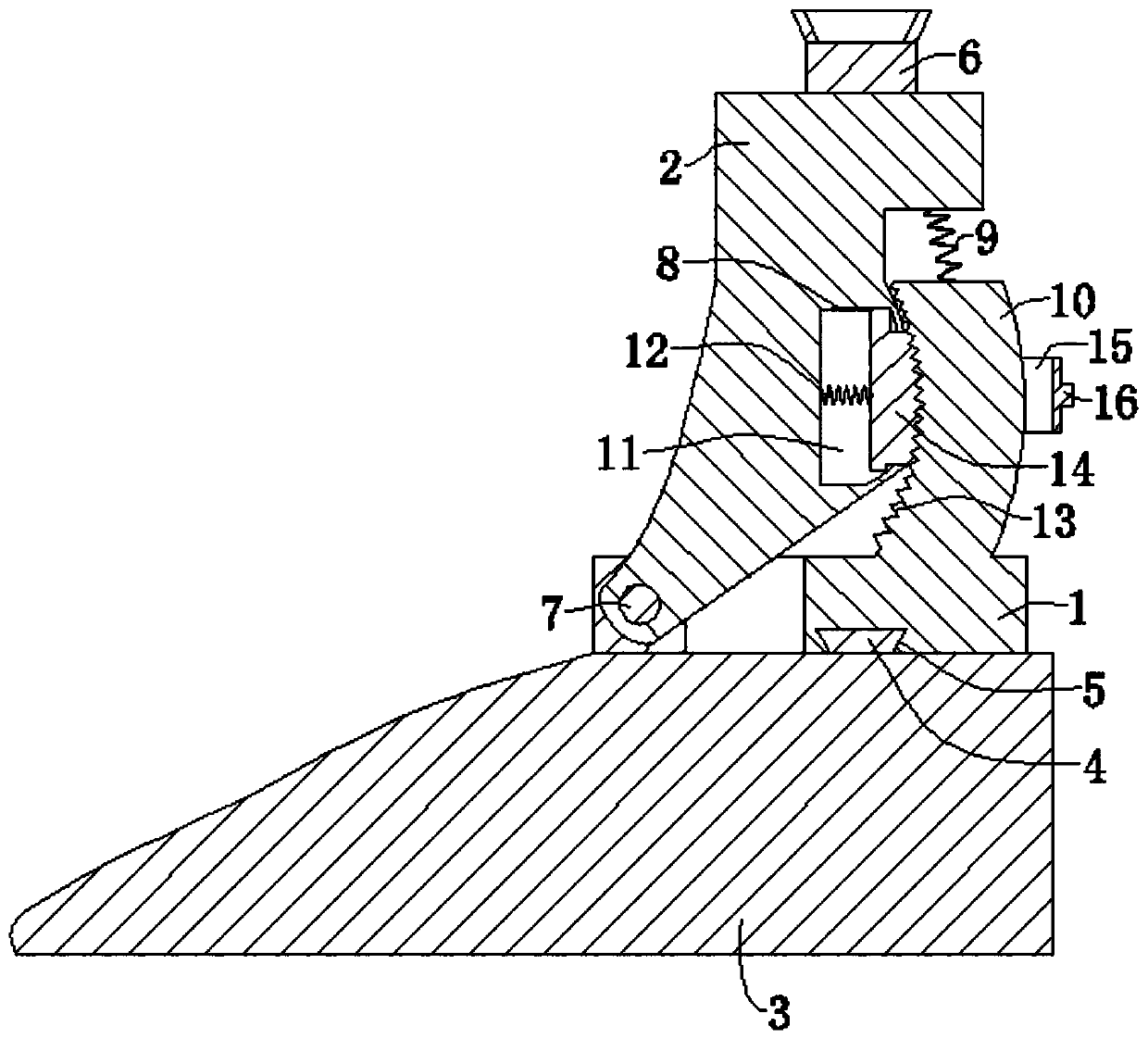
[0027] Embodiment: a kind of mechanical adjustment type prosthetic ankle joint, as figure 1 , 2 As shown, it includes a base 1, an adjustment seat 2, an adjustment button 18 and a buffer spring 9. The top of the adjustment seat 2 is fixed with a connecting block 6, and the top of the connecting block 6 is provided with a slot for inserting the supporting aluminum pipe above the prosthetic foot 3. The bottom of the base 1 is provided with an installation groove 5, and the top of the prosthetic foot 3 is fixed with a square platform 4, and the square platform 4 is inserted in the installation groove 5 and fixed by tightening screws. The central axis of the supporting aluminum tube is on the same straight line as the central axis of the mounting groove 5 . The upper end of the buffer spring 9 is fixed on the adjustment seat 2, the lower end is fixed on the top of the locking seat 10, and the buffer spring 9 is located below the supporting aluminum tube.

[0028] refer to figu...


PUM


Abstract

The invention discloses a mechanical adjustment type artificial limb ankle joint, and belongs to the technical field of artificial limbs. The ankle joint comprises a base, an adjusting seat and an adjusting button, wherein the base is fixed on the artificial foot; a locking seat is fixed to the base; an arc-shaped meshing surface is arranged on one side away from a heel, of the locking seat; the lower part of the front part of the adjusting seat is rotatably connected with the base; an arc surface of which the radian is the same as that of the meshing surface is arranged at the rear part of the adjusting seat, and is in contact with the meshing surface; a cavity is formed in the rear part of the adjusting seat and is opened, and an opening of the cavity is formed in the arc surface of theadjusting seat; a telescopic hole is formed in the middle part of the adjusting button; the adjusting seat penetrates through the telescopic hole up and down; one end of the adjusting button is located in the cavity, and a bite block is fixed to one end of the adjusting button, and is located in the cavity; a compression spring is fixed to one side of the bite block, and bite teeth being meshed with the meshing surface are arranged on the other side of the bite block; and one end of the compression spring is fixed on the inner wall of the cavity, and the other end of the compression spring isfixed on the bite block. Through the adoption of the mechanical adjustment type artificial limb ankle joint disclosed by the invention, the problem that the price of a conventional adjustable artificial limb ankle joint is quite high, so that many amputees cannot afford the conventional adjustable artificial limb ankle joint is solved.

Description

technical field [0001] The invention relates to the technical field of artificial limbs, more specifically, it relates to a mechanically adjustable artificial limb ankle joint. Background technique [0002] Prosthetics are artificial prostheses specially designed and fabricated to compensate for amputees or incompletely missing limbs by means and methods of engineering technology, also known as "prosthetics". Its main function is to replace part of the functions of the lost limbs, so that the amputees can restore a certain ability to take care of themselves and work. Its applicable objects are amputees due to diseases, traffic accidents, industrial accidents, sports trauma and other reasons. Ankle joints are very important components in prosthetic products. [0003] The authorized announcement number is CN105250057B, and the authorized publication date is October 13, 2017. The Chinese patent discloses a hydraulically adjustable prosthetic ankle joint, including a quadrangu...

Claims


Application Information

Patent Timeline
Patent Type & Authority Applications(China)
IPC IPC(8): A61F2/66
CPCA61F2/602A61F2/6607A61F2002/5006A61F2002/5072
Inventor 龚良奇
Owner 湖南海弘医疗科技有限公司
Why Eureka
Try Eureka