Drive device and exhaust heat recovery device

A technology of exhaust heat recovery and driving device, which is applied in the direction of transmission device, gear transmission device, friction transmission device, etc., and can solve problems such as component damage and abnormal sound

Inactive Publication Date: 2019-07-16
FUTABA IND CO LTD
View PDF8 Cites 0 Cited by
  • Summary
  • Abstract
  • Description
  • Claims
  • Application Information

AI Technical Summary

Problems solved by technology

As a result, abnormal sounds may b

Method used


Image

  • Drive device and exhaust heat recovery device
  • Drive device and exhaust heat recovery device
  • Drive device and exhaust heat recovery device

Examples


Embodiment approach

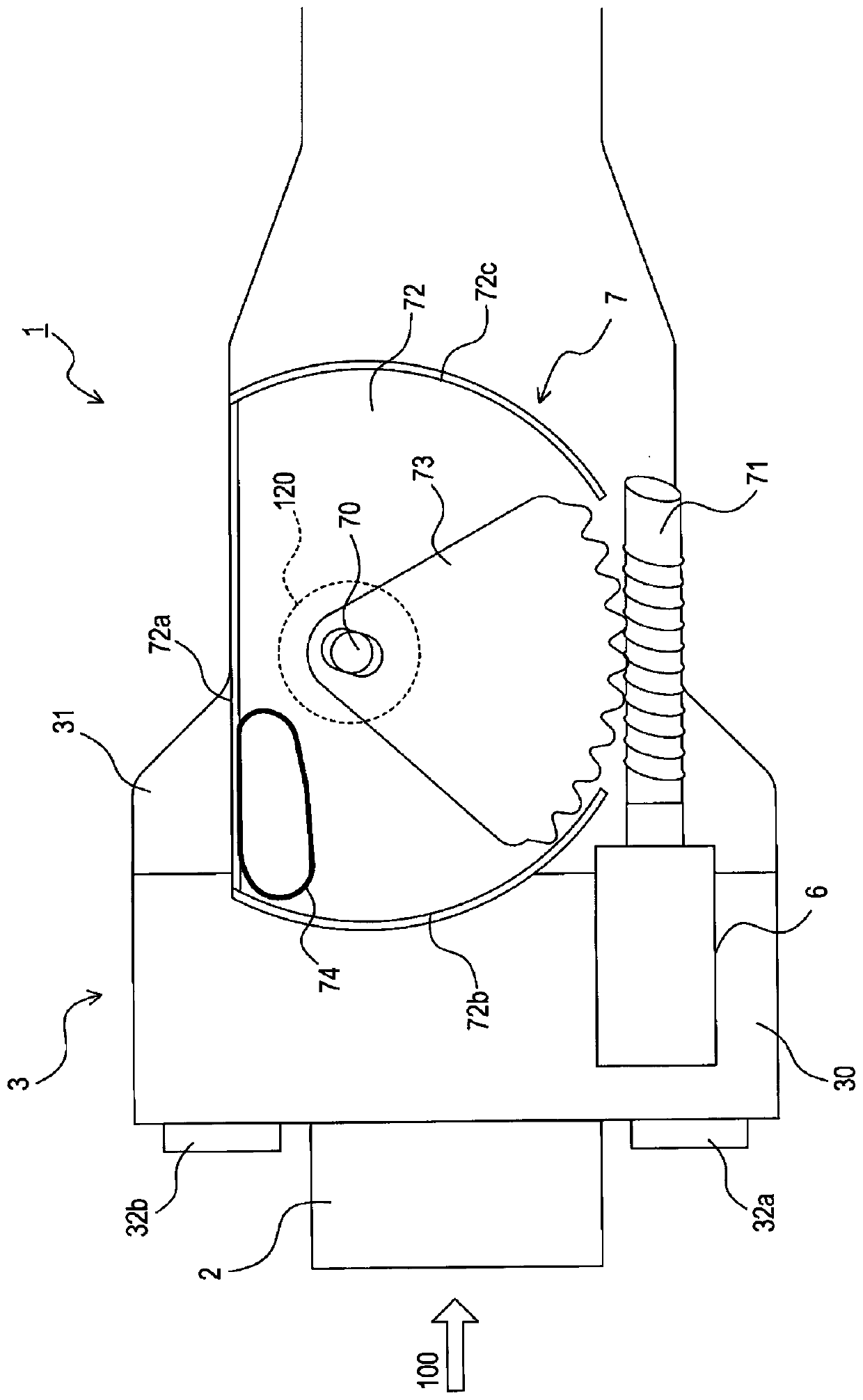
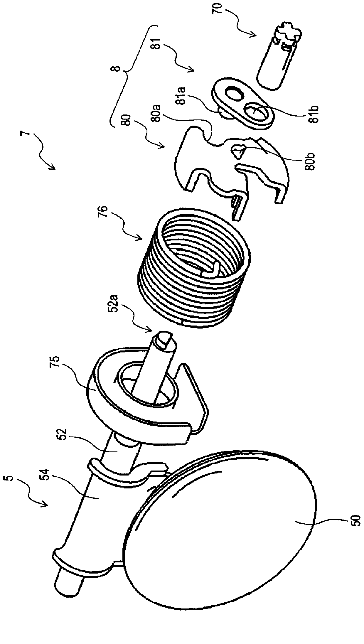
[0089] (1) In the valve opening and closing mechanism 7 of the exhaust heat recovery device 1 of this embodiment, the rotational force of the motor 6 is transmitted to the valve body 50 via the sector gear 73, the worm 71, the drive member 81, etc., as a result, The valve 5 is opened and closed. Furthermore, the sector gear 73 and the worm 71 are disengaged when the drive member 81 reaches the first stop position 81c and the sector gear 73 reaches the first stop position 73a. Then, the sector gear 73 and the worm 71 are disengaged when the driving member 81 reaches the second stop position 81d and the sector gear 73 reaches the second stop position 73b. However, the sector gear 73 and the worm 71 may also be disengaged in one of the above cases, and kept engaged in the other case.

[0090] (2) In the valve opening and closing mechanism 7, the sector gear 73 and the worm 71 are used to transmit the rotational force of the motor 6 to the valve body 5. However, it is also possible...


PUM


Abstract

A drive device drives a drive member and is provided with a power-side gear and a drive-side gear. The power-side gear is driven by a force output from a power source so as to drive the drive member in a range between a first stop position and a second stop position. In addition, the drive-side gear meshes with the power-side gear and transmits the force obtained from the power-side gear to the drive member. Also, the drive-side gear and the power-side gear are configured so as to disengage from each other when the drive member has reached the first stop position and/or the second stop position.

Description

Technical field [0001] The present disclosure relates to a driving device that drives a driving member by force output from a power source, and an exhaust heat recovery device having the driving device. Background technique [0002] There is known an exhaust heat recovery device that exchanges heat between exhaust gas from a vehicle engine and engine coolant. In the exhaust heat recovery device of Patent Document 1, in order to introduce exhaust gas into the heat exchanger when performing heat exchange, it is necessary to switch the exhaust gas flow path using a motor. Specifically, the rotational force output from the motor is transmitted to the valve through the sector gear, thereby opening and closing the valve. [0003] Prior art literature [0004] Patent literature [0005] Patent Document 1: Japanese Patent Laid-Open No. 2016-113979 Summary of the invention [0006] The problem to be solved by the invention [0007] However, in the exhaust heat recovery device in Patent Docume...

Claims


Application Information

Patent Timeline
IPC IPC(8): F01N13/08F01N5/02F02D9/10F16K31/53
CPCF01N5/02F01N13/08F02D9/10F16H2035/006F16H19/001F16H1/16F16K31/041F16K31/535F16K1/2007Y02T10/12F16K31/53F02D9/1065
Inventor 山口裕贵大上裕久
Owner FUTABA IND CO LTD
Why Eureka
Try Eureka