

work machine
A technology of operating machines and operating levers, which is applied to agricultural machinery and implements, agriculture, harvesters, etc., and can solve problems such as increased burdens
- Summary
- Abstract
- Description
- Claims
- Application Information
AI Technical Summary
Problems solved by technology
Method used
Image

Examples
no. 1 approach
[0086] (1) The overall composition of the brush cutter
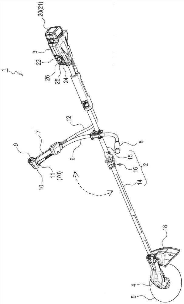
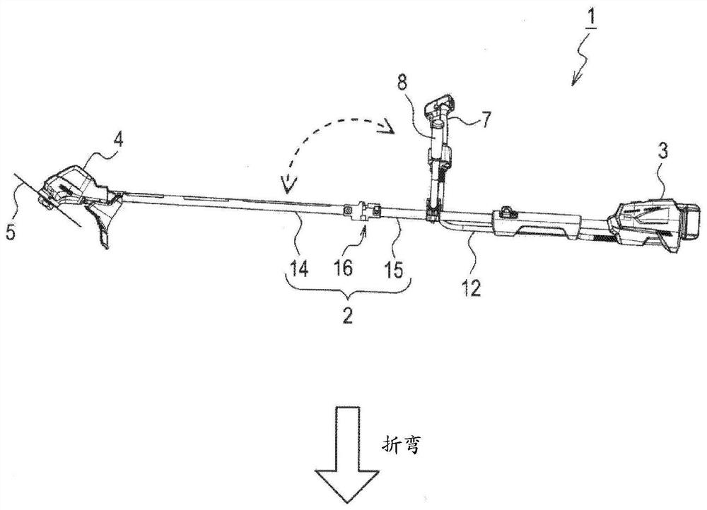
[0087] Such as figure 1 As shown, the brush cutter 1 is provided with a pipe 2 , a rear end unit 3 , a front end unit 4 , and a handle 6 configured as a long cylindrical shape as a whole. The front unit 4 is provided at one of both ends in the longitudinal direction of the pipe 2 , and the rear unit 3 is provided at the other of both ends in the longitudinal direction of the pipe 2 .
[0088] The pipe fitting 2 includes a first pipe material 14 , a second pipe material 15 , and a bent connection portion 16 that connects these respective pipe materials 14 and 15 . The first pipe material 14 is connected to one end side of the bent connecting portion 16 , and the second pipe material 15 is connected to the other end side of the bent connecting portion 16 .
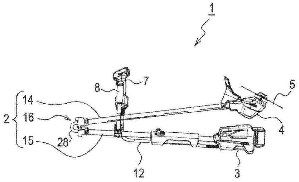
[0089] The bent connecting portion 16 is a cylindrical member as a whole, and is configured to be bendable at a substantially middle portion thereof. Therefore, the...
no. 2 approach
[0177] for Figure 8 The brush cutter 90 of the second embodiment shown has basically the same configuration as that of the brush cutter 1 of the first embodiment except for a part of the configuration including the wiring cutting unit. Therefore, the same reference numerals as those in the first embodiment are attached to the configurations in common with the first embodiment, and description thereof will be omitted, and the differences from the first embodiment will be mainly described.
[0178] In the first embodiment described above, the wiring cutting unit 30 is configured to conduct and cut off the trigger signal line 37 according to the state of the tube 2 . In contrast, in the second embodiment, the wiring cutting unit 92 is configured to conduct and cut off the three power lines 81 , 82 , and 83 according to the state of the pipe 2 .
[0179] Such as Figure 8 As shown, in the brush cutter 90 , both ends of the trigger switch 70 are connected to the motor control un...
no. 3 approach
[0188] In the above-mentioned second embodiment, the electric wires to be cut in the bent state are the three power lines 81 , 82 , and 83 among the eight electric wires laid between the cells. In contrast, in the third embodiment, an example is shown in which the sensor power line 84 and the sensor ground line 85 are cut off instead of the three power lines 81 , 82 , and 83 . It is the same as the second embodiment except that the electrical wiring to be cut is different.
[0189] Such as Figure 10 As shown, the brush cutter 100 of the third embodiment is provided with a wiring cutting portion 102 at the bending connection portion 101 of the pipe 2 . The wiring cutting unit 102 has a pair of connectors 103 and 104 . The first connector 103 is disposed on the first holding portion 31 of the bent connecting portion 101 , and the second connector 104 is disposed on the second holding portion 32 of the bent connecting portion 101 . The pair of connectors 103 and 104 are provi...
PUM
 Abstract
Description
Claims
Application Information