Hold frame for veterinary treatment

A kind of safety frame and veterinary technology, applied in the field of livestock breeding, can solve the problems of cumbersome operation and easily disturbing livestock, etc., and achieve the effect of convenient and quick operation and good adaptability

Active Publication Date: 2019-07-19
高爱文
View PDF7 Cites 7 Cited by
  • Summary
  • Abstract
  • Description
  • Claims
  • Application Information

AI Technical Summary

Problems solved by technology

[0002] When treating livestock, it is necessary to fix the livestock. The safety frame is a fixed frame used to fix the livestock. The traditional safety frame uses a steel structure and elastic straps. The torso of the livestock is fixed with a belt or a fixed rod. The binding belt needs to be fixed with a sprocket, the

Method used


Image

  • Hold frame for veterinary treatment
  • Hold frame for veterinary treatment
  • Hold frame for veterinary treatment

Examples


Embodiment 1

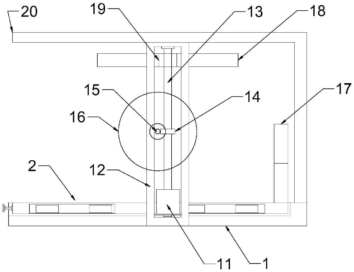
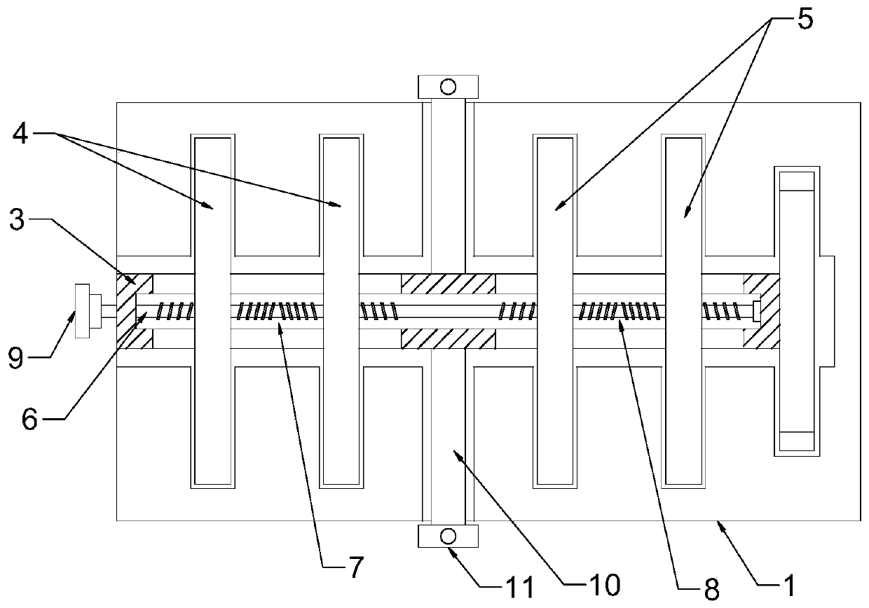
[0021] see Figure 1~4 , in an embodiment of the present invention, a veterinary treatment safety frame includes a bottom plate 1 and a bracket 20; the upper end surface of the bottom plate 1 is nested with a clamping frame 2, and the clamping frame 2 is nested in the bottom plate 1, so that The upper end surface of the base plate 1 is a flat surface, which is convenient for driving livestock to stand on the base plate 1; the clamping frame 2 includes a horizontal chute plate 3 arranged horizontally, and the horizontal chute plate 3 runs through a first limit for limiting the movement of the hind legs of the livestock. The stop rod group 4 and the second stop rod group 5 that limit the movement of the front legs of the livestock, the first stop rod group 4 and the second stop rod group 5 all include a set of stop rods that are arranged oppositely, and the stop rods run through the horizontal The chute plate 3 is vertically arranged with the horizontal chute plate 3; the first ...

Embodiment 2

[0025] please participate figure 1 , The difference between this embodiment and Embodiment 1 is that: an upper limit plate 18 is provided above the clamping frame 2, and the upper limit plate 18 is an arc-shaped surface below the upper limit plate 18, which abuts and limits the back of the livestock for better fixation. livestock; one side of the upper limit plate 18 is fixedly connected with a second sliding block 19, the second sliding block 19 is nested in the vertical chute plate 12, and the two-way screw rod 13 passes through the second sliding block 19 and is connected with the second sliding block 19 threaded connection, when rotating the second adjustment wheel 16 to adjust the height of the clamping frame 2, the upper limit plate 18 is driven to move downward, and the upper and lower sides of the livestock are clamped and limited, which improves the securing effect and is convenient for doctors to operate.

[0026] The contact position of the limit rod and the upper l...


PUM


Abstract

The invention discloses a hold frame for veterinary therapy. The hold frame comprises a bottom plate and a bracket; and a clamping frame is nested on the inner upper end face of the bottom plate, theclamping frame comprises a horizontal slide groove plate which is horizontally arranged, and the horizontal slide groove plate penetrates a first limiting rod group used for limiting the movement of rear legs of livestock and a second limiting rod group used for limiting the movement of front legs of the livestock. According to the invention, the clamping frame which comprises the horizontal slidegroove plate, a first adjusting wheel, a horizontal rotating shaft, the first limiting rod group and the second limiting rod group is arranged to clamp and limit the legs of livestock. Meanwhile, thedistance between limiting rods can be adjusted to adapt to livestock with different body sizes, and the height of the clamping frame is adjusted through a bidirectional screw rod and a worm gear, sothat the clamping frame has better adaptability; By arranging a clamping plate which is fixedly connected to the clamping frame, the synchronous limiting of the legs and head is realized; and meanwhile, by arranging upper limiting plates which are oppositely arranged and synchronously linked, the limiting and clamping of livestock in multiple directions are realized, and the operation is convenient and fast.

Description

technical field [0001] The invention relates to the field of livestock breeding, in particular to a safety frame for veterinary treatment. Background technique [0002] When treating livestock, it is necessary to fix the livestock. The safety frame is a fixed frame used to fix the livestock. The traditional safety frame uses a steel structure and elastic straps. The torso of the livestock is fixed with a belt or a fixed rod. The binding belt needs to be fixed with a sprocket, the fixed rod needs to be fixed with a bolt, and then the head of the livestock is fixed with a fixed rod or a clamping plate. It is also necessary to use a fastening bolt or Fixing the snap-in rod requires multi-step operations, which is cumbersome and easily disturbs the livestock during the operation. [0003] The application provides a stable frame for livestock with simple operation and good adaptability. Contents of the invention [0004] The purpose of the present invention is to provide a sa...

Claims


Application Information

Patent Timeline
IPC IPC(8): A61D3/00
CPCA61D3/00A61D2003/003A61D2003/006
Inventor 高爱文
Owner 高爱文
Why Eureka
Try Eureka