
Rapid phlegm suction device for emergency treatment

A rapid and emergency technology, applied in the direction of suction container, suction device, pumping and pumping system, etc., can solve the problems of poor sputum suction effect of sputum suction device, failure to clear blockage in time, difficulty in ensuring normal breathing, etc., to improve convenience and safety, saving medical resources and costs, and the effect of large negative pressure difference

Active Publication Date: 2019-07-19
THE FIRST AFFILIATED HOSPITAL OF HENAN UNIV OF SCI & TECH
View PDF11 Cites 0 Cited by
  • Summary
  • Abstract
  • Description
  • Claims
  • Application Information

AI Technical Summary

Problems solved by technology

[0004] In view of the above situation, in order to make up for the technical deficiencies existing in the prior art, the present invention provides a rapid sputum suction device for emergency treatment to solve the problem of poor sputum suction effect of existing sputum suction devices, dependence on electric energy, inconvenient reuse and difficult Guaranteed normal breathing and the problem of not being able to clear the blockage in time

Method used


Image

  • Rapid phlegm suction device for emergency treatment
  • Rapid phlegm suction device for emergency treatment
  • Rapid phlegm suction device for emergency treatment

Examples


Embodiment Construction

[0017] The specific implementation manners of the present invention will be described in further detail below in conjunction with the accompanying drawings.

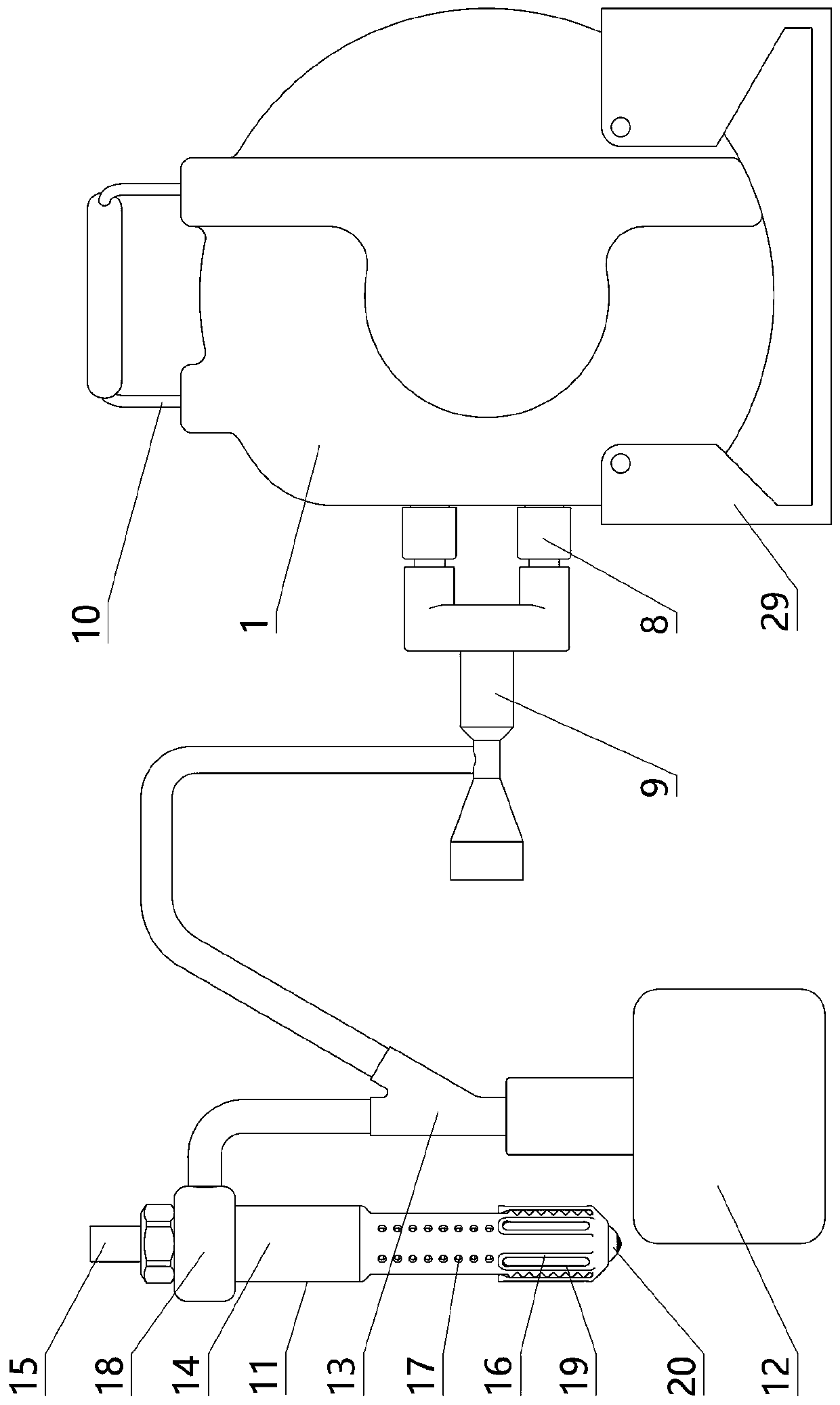
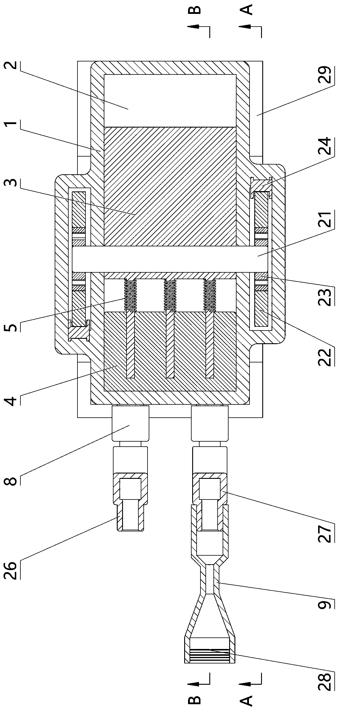
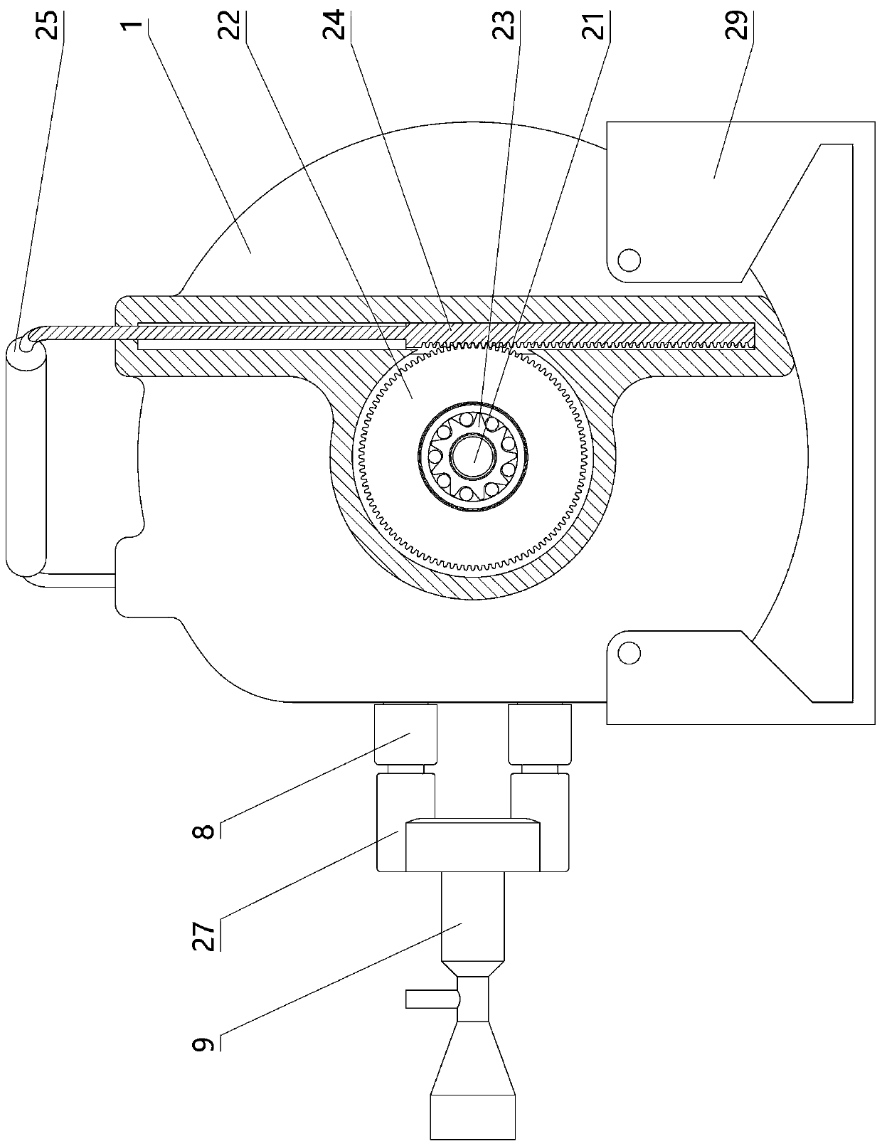
[0018] Depend on Figure 1 to Figure 10 Given, the present invention is made up of suction device and intubation tube assembly, and described suction device comprises casing 1, and the cylindrical cavity 2 that axis is arranged front and rear on casing 1 and is placed in cylindrical cavity 2 and can be arranged along the column. The rotor 3 rotated by the axis of the shaped cavity 2, the front and rear end surfaces of the rotor 3 are attached to the front and rear end surfaces of the cylindrical cavity 2, and the left cavity wall of the cylindrical cavity 2 is a vertical plane and contacts the outer edge surface of the rotor 3; The rotor 3 described above has a left and right sliding horizontal partition 4 placed on the left side of the rotor 3, the left end of the horizontal partition 4 is in contact with the left wall ...


PUM


Abstract

The invention relates to a rapid phlegm suction device for emergency treatment. The device comprises a shell; the shell is equipped with a cylindrical cavity with an axis arranged from front to rear,and a rotor arranged in the cylindrical cavity; the left cavity wall of the cylindrical cavity is a vertical plane and is in contact with the rotor; the rotor is provided with a horizontal partition which slides left and right; the left end of the horizontal partition is in contact with the left chamber wall of the cylindrical chamber; the right end of the horizontal partition is connected to therotor through springs; the shell is provided with gas suction holes and gas pumping holes which communicate with the cylindrical cavity; the gas suction holes are respectively placed above and below the horizontal partition plate and the gas pumping holes are respectively placed above and below the horizontal partition plate; the gas suction holes and the gas pumping holes are respectively connected with duckbill valves; each the duckbill valve corresponding to the gas pumping holes is connected with a venturi tube; the device further comprises a phlegm suction pipe, a phlegm collecting tank and a three-way joint; the phlegm suction pipe is composed of an outer pipe and an inner pipe; two ends of the outer pipe are connected with the inner pipe; one end of the outer pipe is of a corrugatedpipe structure; the outer pipe is provided with a scraping sleeve which sleeves the periphery of the corrugated pipe; the outer pipe is provide with a plurality of phlegm suction holes; and the three-way joint is connected to the phlegm collecting tank, the outer pipe and the throat of the venturi tube through hoses.

Description

technical field [0001] The present invention relates to emergency medical equipment, in particular to a rapid sputum suction device for emergency treatment. Background technique [0002] In the process of emergency treatment, some emergency patients often encounter the problem of mucus blocking the airway due to various reasons, resulting in dyspnea. In this case, it is necessary to suck out the mucus in the patient's body as soon as possible to ensure normal breathing and prevent suffocation. Therefore, the emergency department usually has a sputum aspirator; however, the existing sputum aspirators are mainly electric multifunctional negative pressure sputum aspirators and simple manual sputum aspirators. It is more convenient to use in the consulting room. Once there is a power failure or when going out for first aid, it will be unusable, which will bring inconvenience to the rescue work; the simple manual sputum suction device does not need energy to drive, and uses the p...

Claims


Application Information

Patent Timeline
IPC IPC(8): A61M1/00
CPCA61M1/0003A61M1/0023A61M2205/75
Inventor 韩鹏超季涛涛
Owner THE FIRST AFFILIATED HOSPITAL OF HENAN UNIV OF SCI & TECH
Learn More