Cutting die

A mold and cutting technology, which is applied in metal processing and other directions, can solve the problems of slow efficiency and achieve the effect of low maintenance cost, ingenious design structure, and no takt time

Inactive Publication Date: 2019-07-19
赛能自动化技术(苏州)有限公司
View PDF7 Cites 0 Cited by
  • Summary
  • Abstract
  • Description
  • Claims
  • Application Information

AI Technical Summary

Problems solved by technology

[0002] When making some packaging shells made of PET materials, such as mouse shells and earphone shells, after injection molding, it is often necessary to cut the waste around the circle. When cutting the waste, it is necessary to consider the separation of the waste and the product. , the existing ones still use manual separation, and the efficiency is very slow

Method used


Image

  • Cutting die
  • Cutting die
  • Cutting die

Examples


Embodiment 1

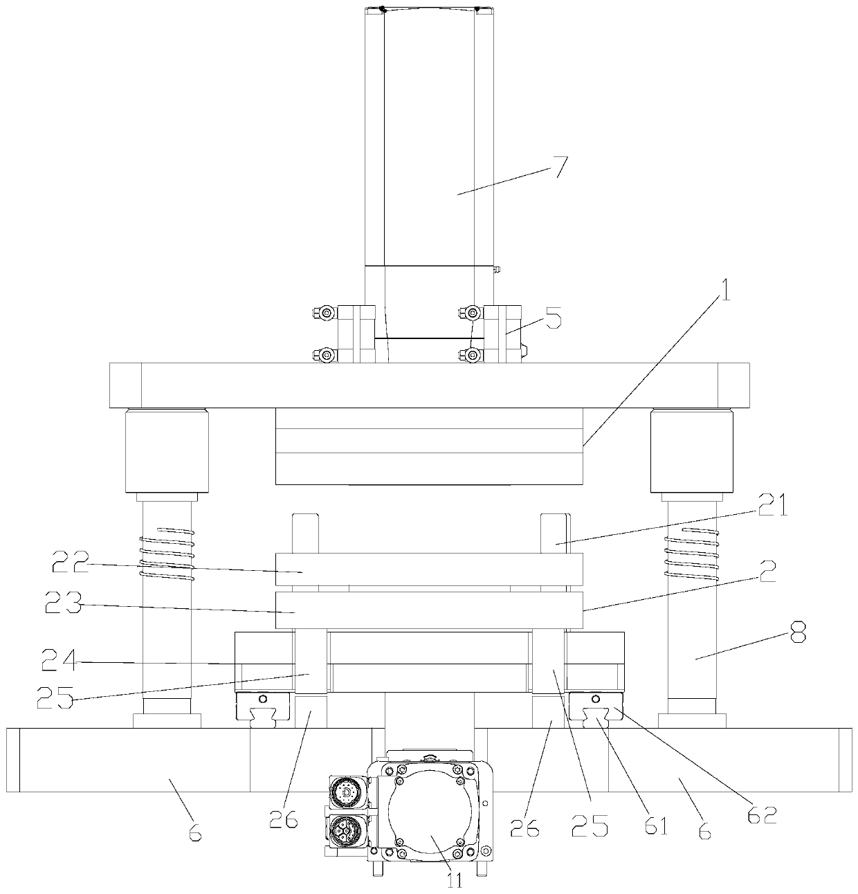
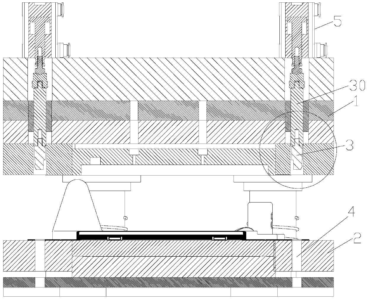
[0022] See figure 1 and 2 As shown, the present embodiment discloses a cutting mold, comprising an upper mold 1 and a lower mold 2, the bottom of the upper mold 1 is provided with an upper cutter, the bottom of the lower mold 2 is provided with a lower cutter, and the upper cutter and the lower cutter are both The same imitation shape, in this embodiment, the upper cutter and the lower cutter are ring-shaped, the lower mold 2 is provided with a guide post 21, and the bottom of the upper mold 1 is provided with a guide hole. When the upper mold 1 is pressed down, the guide post 21 Insert into the guide hole for guidance, and the guide column 21 and the guide hole are correspondingly provided with four;

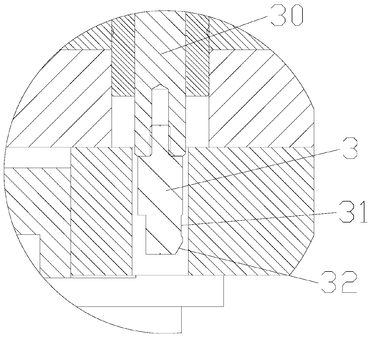
[0023] The upper mold 1 is provided with a retractable material taking column 3, and the lower mold 2 is provided with a positioning hole 4 for the material taking column 3 to extend into, and a through hole corresponding to the positioning hole 4 is also provided on the part ...


PUM


Abstract

The invention discloses a cutting die. The cutting die comprises an upper die and a lower die, wherein an upper cutter is arranged at the bottom of the upper die, a lower cutter is arranged at the bottom of the lower die, telescopic material taking columns are arranged in the upper die, positioning holes allowing the material taking columns to extend into are formed in the lower die, the materialtaking columns are driven to stretch out through air cylinders above the upper die, the bottom of the lower die is connected with a first driving component, and the top of the upper die is connected with a second driving component. According to the technical scheme, the cutting die can be used for material cutting.

Description

technical field [0001] The invention relates to a cutting die. Background technique [0002] When making some packaging shells made of PET materials, such as mouse shells and earphone shells, after injection molding, it is often necessary to cut the waste around the circle. When cutting the waste, it is necessary to consider the separation of the waste and the product. , the existing ones are still manually separated, and the efficiency is very slow. Contents of the invention [0003] The technical problem to be solved by the present invention is to provide a cutting die, which has the characteristics of automatically separating waste materials from products and high efficiency. [0004] In order to solve the above-mentioned technical problems, the technical scheme adopted in the present invention is as follows: a cutting mold, comprising an upper mold and a lower mold, the bottom of the upper mold is provided with an upper cutter, the bottom of the lower mold is provided...

Claims


Application Information

Patent Timeline
IPC IPC(8): B26F1/44B26D7/18B29C37/02
CPCB26D7/18B26F1/44B29C37/02
Inventor 池维升
Owner 赛能自动化技术(苏州)有限公司
Why Eureka
Try Eureka