Automatic plug device and rolling stock power supply automatic connector

A plug-in and automatic technology, which is applied in the direction of railway couplings, transportation and packaging, railway car body parts, etc., can solve the problems of low accuracy rate and inability to effectively provide power supply, so as to eliminate up and down movement and solve the problem of unconfigured power source and power supply problems, improve the effect of accurate docking

Active Publication Date: 2020-09-01
SHANGHAI BAOYE CONSTR INDAL FURNACE ENG TECH +1
View PDF5 Cites 0 Cited by
  • Summary
  • Abstract
  • Description
  • Claims
  • Application Information

AI Technical Summary

Problems solved by technology

[0004] For this reason, the technical problem to be solved by the present invention is to overcome the problems of low docking accuracy and inability to effectively provide power in the prior art, thereby providing an automatic plug device and a rolling stock power supply with high docking accuracy and effective power supply automatic connector

Method used


Image

  • Automatic plug device and rolling stock power supply automatic connector
  • Automatic plug device and rolling stock power supply automatic connector
  • Automatic plug device and rolling stock power supply automatic connector

Examples


Embodiment 1

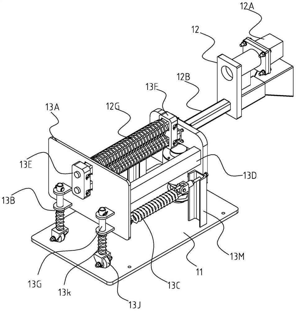
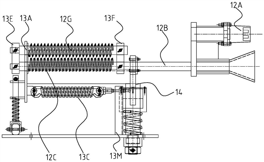
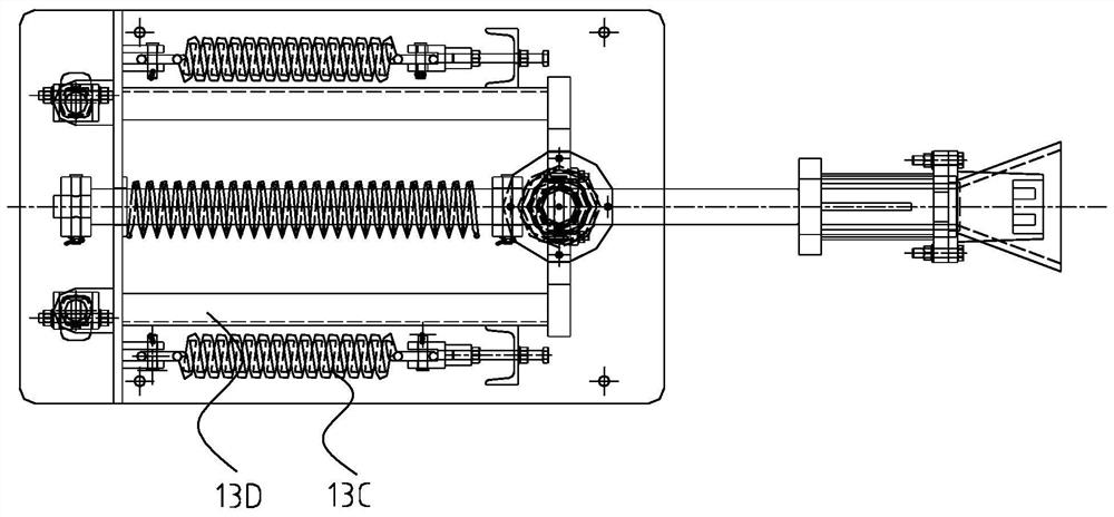
[0028] Such as figure 1 and figure 2 as well as image 3 As shown, this embodiment provides an automatic plug device, including a base 11, on which a plug assembly 12, a rotary reset assembly, and an automatic plug rotary member 14 are provided, wherein the plug assembly 12 includes a plug 12A and is connected with the A slide bar assembly connected to the plug 12A, the slide bar assembly includes a slide bar 12B and a first elastic element 12C located on the slide bar 12B, the plug 12A is connected between the slide bar 12B and the first elastic element Driven by 12C, it can move along the length direction of the base 11. The rotary reset assembly includes a slide plate 13A movably connected with the slide bar 12B, a rotating assembly 13B and a reset element 13C, and the rotating assembly 13B and the reset element 13C are all connected to the sliding plate 13A, and the sliding plate 13A and the rotating assembly 13B roll around the automatic plug rotating member 14 on the ...

Embodiment 2

[0037] Such as Figure 7 and Figure 8 As shown, this embodiment provides an automatic power supply connector for rolling stock, including the automatic plug device and socket assembly 15 described in Embodiment 1, and the plug 12A in the automatic plug device and the socket in the socket assembly 15 15A are interconnected.

[0038] The automatic power supply connector for rolling stock in this embodiment includes the automatic plug device and the socket assembly 15 described in Embodiment 1, and the plug 12A in the automatic plug device is kept horizontal to the socket assembly 15, which is beneficial to all The plug 12A is connected to the socket 15A in the socket assembly 15, since the socket assembly 15 is installed on the locomotive, it can provide power for the whole operation.

[0039] The socket assembly 15 also includes a second connecting plate 15B and a guide rod 15C fixed on the second connecting plate 15B, and the socket 15A is fixed on the second connecting pla...


PUM


Abstract

The invention relates to an automatic plug device and a locomotive and car power supply automatic connector. The automatic plug device comprises a base; a plug component, a rotation resetting component and an automatic plug rotation piece are arranged on the base, wherein the plug component comprises a plug and a sliding rod component connected with the plug; the sliding rod component comprises asliding rod and a first elastic element positioned on the sliding rod; the plug can move in a length direction of the base under the driving of the sliding rod and the first elastic element; the rotation resetting component comprises a sliding plate, a rotation component and a resetting element, wherein the sliding plate is movably connected with the sliding rod; the rotation component and the resetting element are both connected with the sliding plate; and the sliding plate and the rotation component roll on the base around the automatic plug rotation piece. According to the automatic plug device and the locomotive and car power supply automatic connector, the docking accuracy is high, and power supply can be effectively provided.

Description

technical field [0001] The invention relates to the technical field of rail transportation, in particular to an automatic plug device and an automatic power supply connector for rolling stock. Background technique [0002] The mixed iron car is responsible for the transportation of molten iron between the blast furnace and the steelmaking plant. It is a key link in the iron and steel logistics. The mixed iron car is a kind of unpowered rail vehicle without a power source and a braking device. Usually, it needs to be parked. Manually placing wheel stoppers to prevent vehicles from slipping is not only expensive and labor-intensive, but also has many potential safety hazards, and does not meet the automated program control requirements for building an "efficient and humanized smart freight yard station". In order to realize unmanned operation, the mixed railway car must be equipped with a remote electronically controlled braking device. At the same time, the most critical poin...

Claims


Application Information

Patent Timeline
Patent Type & Authority Patents(China)
IPC IPC(8): B61G5/10
CPCB61G5/10
Inventor 万小兵周勤鲁少刚陆剑余维勇
Owner SHANGHAI BAOYE CONSTR INDAL FURNACE ENG TECH
Why Eureka
Try Eureka