

Reinforcement cage lifting device
A steel cage and spreader technology, applied in the direction of load hanging components, transportation and packaging, etc., can solve problems such as butt joints and difficulties of easily deflected steel cages, and achieve the effect of ensuring progress and quality, easy docking, and ensuring verticality
Inactive Publication Date: 2011-06-15
HENAN MINE CRANE
View PDF5 Cites 12 Cited by
- Summary
- Abstract
- Description
- Claims
- Application Information
AI Technical Summary
Problems solved by technology
The purpose of the present invention is to provide a steel cage hanger to solve the problem that the existing steel cage is easy to deflect when hoisting, which makes it difficult to connect the steel cage
Method used
View moreImage
Smart ImageViewing Examples

Examples
Embodiment Construction
Login to View More PUM
 Abstract
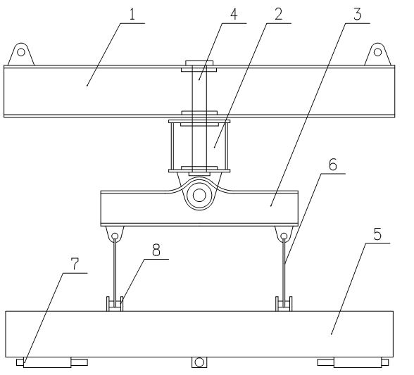
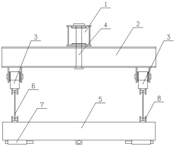
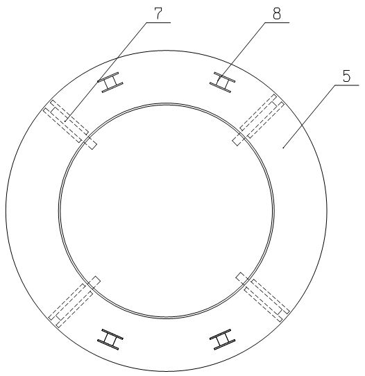
The invention discloses a reinforcement cage lifting device, which comprises an upper beam, a middle beam, lower beams and an annular beam for connecting a reinforcement cage, wherein the two ends of the upper beam are fixed with a lifting lug for connecting a crane respectively; the middle beam is hinged to the center of the upper beam through a connecting shaft vertically inserted into the middle beam; the lower beams are hinged to the two ends of the middle beam through pin shafts horizontally inserted into the centers of the lower beams respectively; and the annular beam is horizontally suspended on the lower beams by corresponding suspenders. When in use, the reinforcement cage lifting device connects the reinforcement cage to the annular beam in a suspension way, and when the reinforcement cage is jointed, can conveniently drive the reinforcement cage to horizontally rotate, flexibly regulate the vertical angel of the reinforcement cage and ensure the verticality of the reinforcement cage in a jointing process to easily and rapidly finish the jointing of the reinforcement cage, increase the jointing speed of the reinforcement cage and improve the jointing quality of the reinforcement cage by hinging fit among the upper, middle and lower beams, thereby ensuring the progress and quality of pile foundation construction.
Description
Steel cage spreader technical field The invention relates to a sling used for hoisting a reinforcement cage in pile foundation construction. Background technique At present, in the pile foundation construction of bridges, high-rise buildings or high-speed railways, it is necessary to dig deep pile holes first, and then put a reinforcement cage in the pile holes and then pour cement to form a reinforced concrete structure. Because the pile holes are very deep, the reinforcement cages need to be fabricated in sections, and then lowered into the pile holes by a crane, and the main bars on the two reinforcement cages are manually screwed through the connecting sleeves to form a reinforcement skeleton. The existing reinforcement cages are hoisted by ropes or hooks, which are easy to stretch and deform the reinforcement cages. In addition, the reinforcement cages are prone to deflection during the transportation process, making adjustment difficult, and the upper and lower reinf...
Claims
Login to View More Application Information
Patent Timeline
 IPC IPC(8): B66C1/10B66C1/12B66C1/62B66C13/08
Inventor高明利任海涛
OwnerHENAN MINE CRANE