Welding method and equipment for multifunctional threaded fastener

A technology of threaded fasteners and welding methods, applied in welding equipment, welding equipment, auxiliary welding equipment, etc., can solve the problems of high cost, inability to take out, increase production cost, etc., and achieve low welding pressure, good welding quality, and welding. Efficient effect

Active Publication Date: 2016-08-24
何强
View PDF16 Cites 13 Cited by
  • Summary
  • Abstract
  • Description
  • Claims
  • Application Information

AI Technical Summary

Problems solved by technology

If the torque is large, it far exceeds the requirements for the welding strength of threaded fasteners, and if it is poor, the threaded fasteners will fall off, causing rework, increasing production costs, and wasting manpower and material resources.
When the product structure is complex and the number of assembled parts is large, if the threaded fasteners are found to fall off during the final assembly of the car, it will not only affect the assembly progress of the entire car assembly line
Due to the complex structure of the body, threaded fasteners may fall into the body and cannot be taken out. In this case, rework is very difficult, and the body can only be scrapped.
The utility model pate

Method used


Image

  • Welding method and equipment for multifunctional threaded fastener
  • Welding method and equipment for multifunctional threaded fastener
  • Welding method and equipment for multifunctional threaded fastener

Examples


Embodiment 1

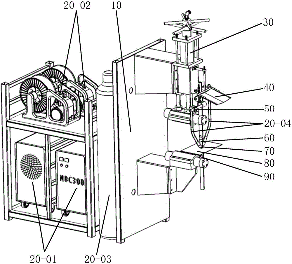
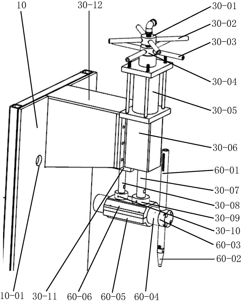
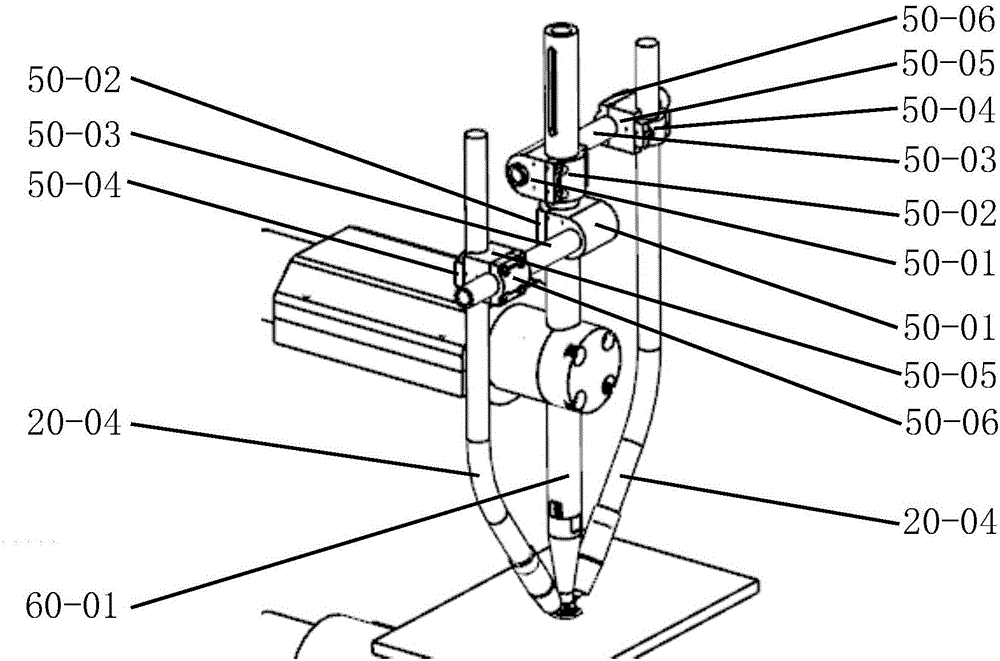
[0063] Embodiment 1: Welding power supply (20-01) and wire feeding mechanism (20-02) are placed at the rear of the body (10). What is used here is a welding machine with the wire feeding mechanism outside the power supply. Of course, the wire feeding mechanism can also be used Welder inside the power supply. One welding power supply (20-01) can be placed at the rear of the body (10), or two, three, four or even more can be placed squarely. Correspondingly, the clamping welding torch (20-04) can also be equipped with Hands, two, three, four or even more. The welding power supply (20-01) placement area is provided with heat dissipation holes or heat dissipation windows to facilitate the heat dissipation of the welding power supply. And when the welding power source needs to weld other products, it should be easy to take out from the body (10). There is a welding terminal at the rear of the body (10), and the output terminal of the welding power supply (20-01)—the positive or n...

Embodiment 2

[0076] Embodiment 2: This embodiment is the technical scheme of welding bolts, such as Figure 6 shown. Except for the positioning mechanism (90), other structures of the device are consistent with Embodiment 1. The lower adjusting rod (90-05) of the positioning mechanism (90) is connected with the bolt positioning rod (90-11), and the bolt insulating sleeve (90-10) of high-strength insulating material is arranged in the bolt positioning rod (90-11). Positioning holes for positioning bolts (70-01) are arranged in the insulating sleeve (90-10). The upper workpiece (80-01) of the bolt positioning rod (90-11) is the positioning surface in the up and down direction, and the pressing surface at the lower end of the pressing rod (60-02) is larger than the bearing surface (70-01) of the bolt (70-01). -1) Small. Since the bolt (70-01) does not need bumps, the bearing surface (70-01-1) of the bolt (70-01) can also be made smaller than the projection welding bolt.

[0077] In additi...

Embodiment 3

[0079] Embodiment 3: This embodiment is a technical scheme for welding pipe fittings with holes at the welding place and nuts, such as Figure 7 shown. This embodiment adopts a TIG welding machine, and the welding torch of the welding machine is installed on the lower adjustment column, and a positioning frame of a round pipe (80-02) is added in addition. The positioning frame (90-12) is connected with the lower adjustment column concave block (90-06) above the lower adjustment column clamp block (90-07). There is an adjusting gasket between the positioning frame (90-12) and the lower adjusting column clamping block (90-07), which is used to adjust the position of the vertical direction of the positioning frame (90-12). Adjustment hole is arranged on the spacer connecting block (90-12-3), is used for adjusting the position of spacer (90-12) front and rear direction. The plane above the positioning longitudinal bar (90-12-1) is the positioning surface of the round pipe (80-02...


PUM


Abstract

The invention discloses a welding method and equipment for a multifunctional threaded fastener. The welding method comprises MAG welding, TIG welding, MIG welding, stud welding and MIG brazing. The threaded fastener and a workpiece are positioned by a positioning mechanism of the equipment, a welding gun is clamped by a clamping mechanism, a pressing force is transmitted to a pressing mechanism by a power component, the threaded fastener and the workpiece are pressed by the pressing mechanism, the welding gun is driven to move downwards at the same time, and the threaded fastener and the workpiece are welded by a welding mechanism. Compared with existing arc welding equipment for welding the threaded fastener, the method and the equipment have the advantages that the efficiency is improved by 2 to 4 times; moreover, the problems of poor stability of conventional resistance projection welding of the threaded fastener, incapability in welding medium- and high-carbon steel, alloy steel, dissimilar metals and dissimilar materials, incapability of welding on the sidewall of a U-shaped sheet metal part, various hollow and solid pipe fittings and thick plates, incapability of abreast welding of the threaded fastener and the workpiece and the like are solved. In addition, the invention further provides MIG-brazed and flame-brazed fastener and a workpiece used for welding a threaded fastener and positioned by a light beam.

Description

Technical field [0001] The invention relates to a welding method and equipment for threaded fasteners. Background technique [0002] The welding of threaded fasteners is widely used in manufacturing fields, such as automobiles, motorcycles, electric bicycles, construction machinery, communication equipment, high-speed rail trains, aircraft, etc. The welding method of traditional threaded fasteners is resistance projection welding, and the welding equipment adopts resistance spot welding machine (also called resistance projection welding machine). This welding method needs to process the welded ends of the threaded fasteners into bumps before welding, and weld the threaded fasteners with bumps to other sheet metal parts. Since the heat source of this welding method is resistance heat, it is called resistance projection welding. The reason why there are bumps is to concentrate the current during welding in order to increase the intensity of electric energy, otherwise, weldin...

Claims


Application Information

Patent Timeline
IPC IPC(8): B23K37/02B23K37/04
CPCB23K9/16B23K9/20B23K9/32B23K9/321B23K37/00B23K37/006B23K37/02B23K37/04
Inventor 何强
Owner 何强
Why Eureka
Try Eureka