Processing method for high-precision thin step shaft and grinding chuck for processing method

A processing method and technology for stepped shafts, which are applied in the field of shaft parts processing, can solve the problems of step end face grinding of difficult and thin stepped shafts, inability to realize centerless grinding, and poor outer diameter, so as to achieve stable processing quality and save raw materials and processing time. , the effect of improving processing efficiency

Active Publication Date: 2014-12-24
贵州凯星液力传动机械有限公司
View PDF7 Cites 21 Cited by
  • Summary
  • Abstract
  • Description
  • Claims
  • Application Information

AI Technical Summary

Problems solved by technology

However, this processing technology uses centerless grinding. First, the stepped shaft is ground into a cylindrical shaft with a large diameter, and then the outer circle with a small diameter is ground. This processing method is difficult to achieve thin-walled stepped shafts with centerless grinding. The grinding of the step end face of the step shaft, especially when there is a high position tol

Method used


Image

  • Processing method for high-precision thin step shaft and grinding chuck for processing method
  • Processing method for high-precision thin step shaft and grinding chuck for processing method
  • Processing method for high-precision thin step shaft and grinding chuck for processing method

Examples


Embodiment Construction

[0037] The technical solution of the present invention is further described below in conjunction with the accompanying drawings of the embodiments, but the scope of protection is not limited to the description.

[0038] A processing method of a high-precision thin stepped shaft according to the present invention mainly includes the following method steps:

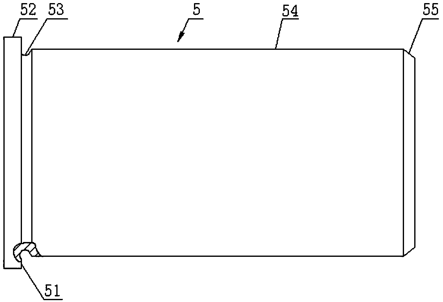
[0039] (1) Material preparation: such as figure 1 As shown, the blanking of the round bar is carried out according to the length of the step outer circle 52 and the length of the step axis outer circle 54, and the material is 20CrMnTi;

[0040] (2) Heat treatment: normalize the round bar or forging prepared in step (1) at a temperature of 950°C to 970°C, air cooling, and a hardness of HBS170 to 210;

[0041] (3) Car processing: the steps of the car processing method are as follows:

[0042] a. Clamp the outer circle of the bar, turn one end of the bar, and drill the center hole;

[0043] b. Clamp one end of the bar, the ...


PUM

PropertyMeasurementUnit
Surface hardnessaaaaaaaaaa

Abstract

The invention provides a processing method for a high-precision thin step shaft and a grinding chuck for the processing method. The processing method mainly comprises the following steps: (1) preparing materials; (2) performing heat treatment; (3) performing end face and excircle turning and center drilling; (4) performing the heat treatment; (5) performing surface treatment; (6) performing abrasive machining on center holes in both ends of the thin step shaft; (7) grinding a step excircle and a step end face; (8) performing precision grinding; the grinding chuck comprises a clamping disk and a deflector rod arranged on the clamping disk; a chuck hole is formed in the middle part of the clamping disk; three inclined holes are evenly distributed, along the peripheral direction of the chuck hole, in the clamping disk; a lifting pin is arranged in each oblique hole, and is locked through an inner hexagon cone point set screw. According to the processing method and the grinding chuck provided by the invention, the thin step shaft is clamped through the grinding chuck to perform grinding on the excircle and the end face, and the processing quality is stable; meanwhile, traditional processes for cutting the thin step shaft into two pieces, performing abrasive cut-off on a rear end face and removing burrs are reduced in the processing technology of the processing method provided by the invention, so that the raw materials are greatly saved, and meanwhile, the processing efficiency is improved.

Description

technical field [0001] The invention relates to a processing method for a high-precision thin stepped shaft and a grinding chuck, belonging to the technical field of processing shaft parts. Background technique [0002] The step shaft is the most widely used shaft part at present, and the choice of its processing method directly affects the processing quality of the shaft and affects the performance of the shaft. There are many existing processing methods for shafts, but there is no relatively mature processing method for processing thin stepped shafts, such as figure 1 As shown, when grinding the stepped shaft outer circle 55 and the stepped end face 51 of the thin stepped shaft 5, if the stepped outer circle 52 of the thin stepped shaft 5 is clamped with a universal chicken heart chuck, the stepped shaft of the thin stepped shaft 5 cannot be ground The end of the outer circle 55 and the step end face 51, in order to be able to grind the end of the step shaft outer circle ...

Claims


Application Information

Patent Timeline
IPC IPC(8): B23P15/00B24B41/06
CPCB23P15/00B24B41/06B24B41/062
Inventor 叶义书
Owner 贵州凯星液力传动机械有限公司
Why Eureka
Try Eureka