Electric valve and cooling system using electric valve

A technology of electric valves and spools, applied in the direction of valve operation/release devices, refrigerators, multi-way valves, etc., can solve the problems of unable to adjust the throttling amount of refrigerant, difficult to achieve stable temperature and energy saving, and difficult to quickly cool down the room, etc.

Active Publication Date: 2020-07-07
SAGINOMIYA SEISAKUSHO INC
View PDF1 Cites 0 Cited by
  • Summary
  • Abstract
  • Description
  • Claims
  • Application Information

AI Technical Summary

Problems solved by technology

In this way, in the case of using a capillary tube (C.Tube), the throttling amount of the refrigerant cannot be freely adjusted like an electronic expansion valve, so it is difficult to perform fine temperature control, it is difficult to quickly cool the room, or it is difficult to stabilize the temperature. Energy saving, etc.

Method used


Image

  • Electric valve and cooling system using electric valve
  • Electric valve and cooling system using electric valve
  • Electric valve and cooling system using electric valve

Examples


Embodiment Construction

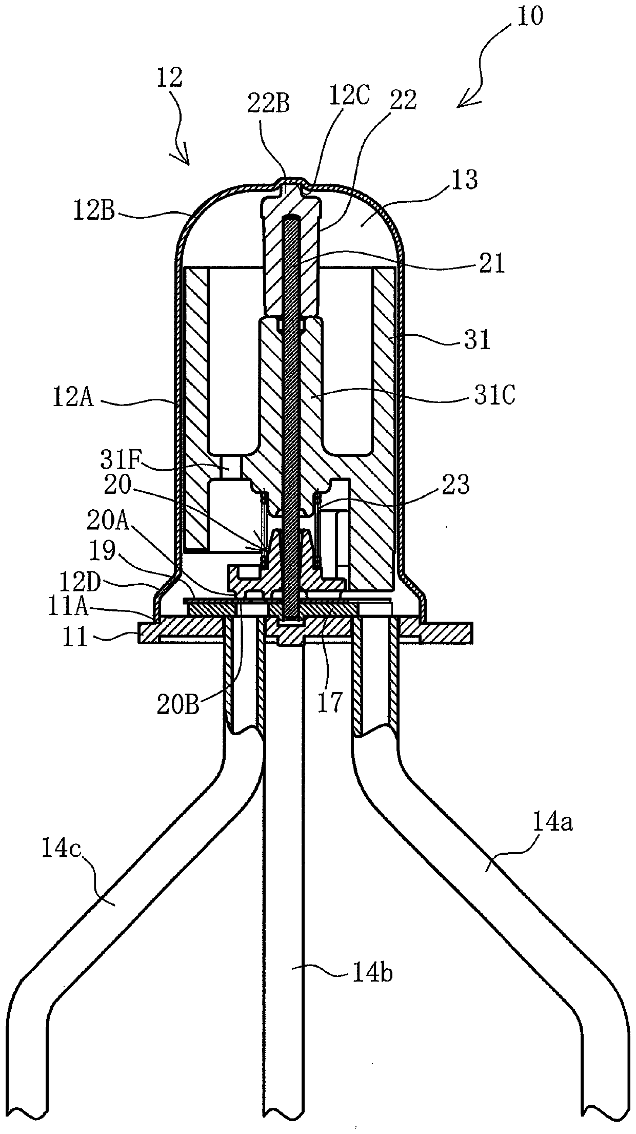
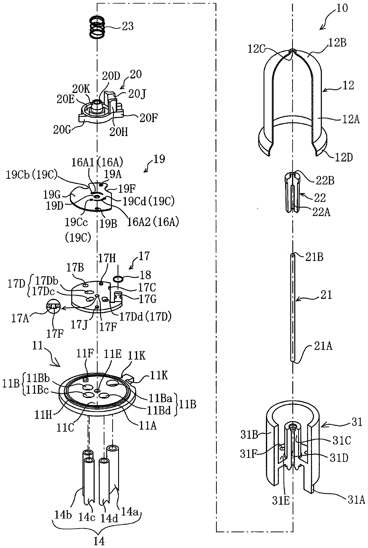
[0055] Hereinafter, an electric valve according to a first embodiment will be described with reference to the drawings. figure 1 is a cross-sectional view of the electric valve of the first embodiment, figure 2 yes figure 1 An exploded perspective view of the electric valve shown. In addition, in this specification, "upper" or "lower" means figure 1 The motor valve 10 shown is specified as a reference.

[0056] Such as figure 1 As shown, the electric valve 10 accommodates driving mechanisms such as a rotor 31 described later, has a disc-shaped bottom cover member 11, and a housing 12 airtightly welded on the bottom cover member 11, and the housing 12 A valve chamber 13 with an airtight chamber structure is formed on the inner side of the valve body. In addition, a stator assembly (not shown) to be described later is mounted on the outer periphery of the case 12 .

[0057] Such as figure 2As shown, in order to securely obtain the concentricity between the rotor hou...


PUM


Abstract

The present invention provides an electric valve capable of controlling temperature with high precision without enlarging the installation space of an expansion valve and suppressing power consumption. In the electric valve that controls the throttling flow rate by rotating a single valve element facing the valve seat surface around an axis, an arc-shaped valve is formed on the valve seat surface in the same direction as the rotation direction of the valve element. The first groove and the second groove extend and gradually change in groove width, and the first inlet port and the first outlet port communicating with the first groove are arranged on the valve seat surface side of the valve element through the first inlet port. The main valve part communicated with a groove is formed on the sealing surface of the main valve part to extend in an arc shape in the same direction as the rotation direction of the valve core and to make the second inlet port and the second groove. The second outlet port communicates with the communicating groove.

Description

technical field [0001] The present invention relates to an electric valve used as a flow control valve of a freezer or a refrigerator, and a cooling system using the electric valve. Background technique [0002] Today, in cooling systems such as household refrigerators, such as Figure 17 As shown, there is known a cooling system that uses a three-way valve (3-way valve) to switch the refrigerant supplied to the refrigerator (R.Evap) and the freezer (F.Evap). system. According to this cooling system, temperature control can be performed by cooling the refrigerator compartment and the freezer compartment alternately. [0003] However, in this cooling system, the refrigerant supplied to the cooler (R. Evap) for the refrigerator compartment and the cooler (F. Evap) for the freezer compartment is expanded in the capillary tube (C. Tube). In this way, in the case of using a capillary tube (C.Tube), the throttling amount of the refrigerant cannot be freely adjusted like an elect...

Claims


Application Information

Patent Timeline
Patent Type & Authority Patents(China)
IPC IPC(8): F16K11/16F16K11/074F16K31/04F25B41/06
CPCF16K11/074F16K11/16F16K31/04
Inventor 笠井宣铃木毅敏
Owner SAGINOMIYA SEISAKUSHO INC
Why Eureka
Try Eureka