Cooling device for mechanical parts

A technology for cooling devices and mechanical parts, applied in the field of cooling of mechanical parts, can solve problems such as cracking, easy deformation, oxidation, etc., and achieve the effect of preventing deformation

Active Publication Date: 2020-06-12
CHANGZHOU INST OF MECHATRONIC TECH
View PDF6 Cites 0 Cited by
  • Summary
  • Abstract
  • Description
  • Claims
  • Application Information

AI Technical Summary

Problems solved by technology

[0003] In my country's heat treatment enterprises, mechanical parts are prone to defects such as deformation, cracking, and oxidation during the quenching and cooling process. Therefore, a cooling device suitable for quenching and cooling devices for thin-walled parts is urgently needed in the market.

Method used


Image

  • Cooling device for mechanical parts
  • Cooling device for mechanical parts
  • Cooling device for mechanical parts

Examples


Embodiment 1

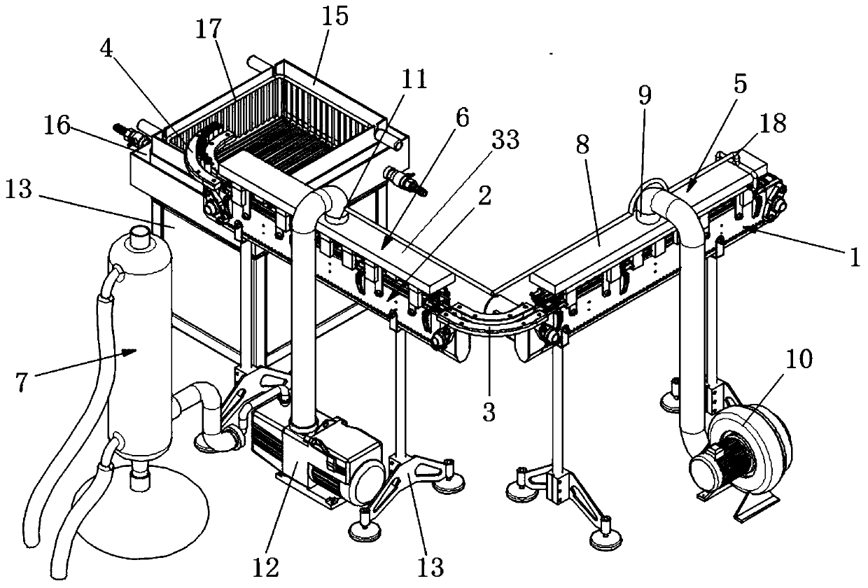
[0039] The present invention provides as attached Figure 1-8 The cooling device for mechanical parts shown includes a first transmission mechanism 1 and a second transmission mechanism 2, the first transmission mechanism 1 is connected to the second transmission mechanism 2 through the first guide groove 3, and the end of the second transmission mechanism 2 A second guide groove 4 is provided.

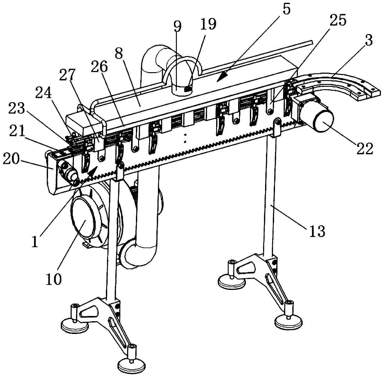
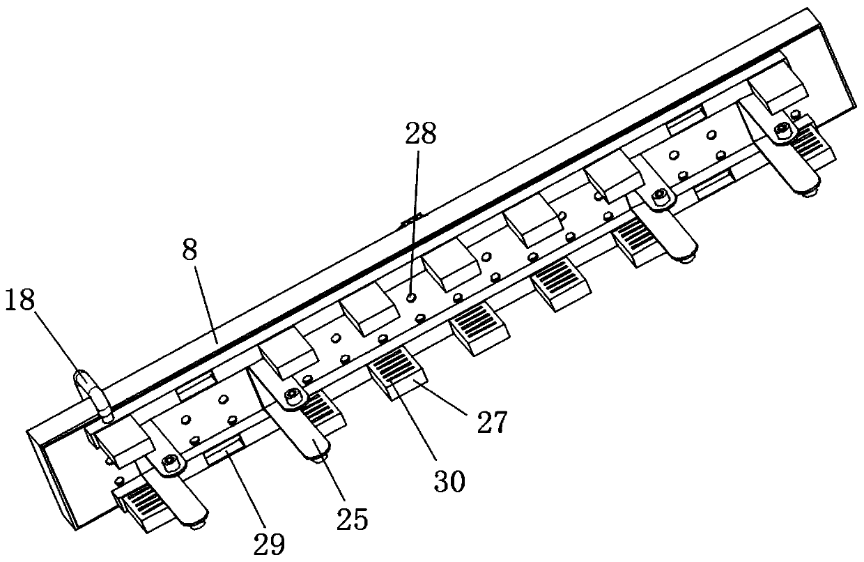
[0040] The first conveying mechanism 1 is provided with a warm air cooling mechanism 5, and the warm air cooling mechanism 5 includes a warm air box 8 fixed on the first conveying mechanism 1. The warm air box 8 can be made by splicing aluminum plates. A U-shaped connector 25 is fixed on the first transmission mechanism 1, and the two bottom ends of the first U-shaped connector 25 are connected with the first transmission mechanism 1 through bolts. The air hole 28, the top of the heater box 8 is provided with an air inlet 9, the air inlet 9 is connected with a blower 10 through a pip...

Embodiment 2

[0044] The difference with embodiment 1 is:

[0045] as attached figure 1 And attached figure 2 As shown, the first transmission mechanism 1 includes a fixed frame 20, the bottom of the fixed frame 20 is provided with a support foot 13, the support foot 13 props up the fixed frame 20 to facilitate the operation of the staff, and the two shafts on the fixed frame 20 are wrapped Covered with crawler belts 21, and one of the shafts is connected with a driving motor 22, the shaft is rotated by the driving motor 22, and the two shafts cooperate to drive the crawler belts 21 to rotate. Both sides of the fixed frame 20 are connected with guide rods 24 through a plurality of guide rod fixing parts 23, and the guide rods 24 on both sides are parallel to each other, and the mechanical parts can be neatly arranged on the crawler belt of the first transmission mechanism 1 through the guide rods 24. 21, it can also prevent mechanical parts from falling out of the first conveying mechani...


PUM


Abstract

The invention discloses a cooling device for mechanical parts, and relates to the technical field of cooling of mechanical parts. The cooling device comprises a first conveying mechanism and a secondconveying mechanism which are connected, a second guide groove is formed in the tail end of the second conveying mechanism, the first conveying mechanism is provided with a warm air cooling mechanism,the warm air cooling mechanism comprises a warm air box fixed on the first conveying mechanism, an air inlet is formed in the top of the warm air box, a heating mechanism is arranged in the air inlet, the air inlet is connected with an air blower through a pipeline, a cold air cooling mechanism is arranged on the second conveying mechanism, the cold air cooling mechanism is fixed on a cold air box on the second conveying mechanism, an air outlet is formed in the top of the cold air box, the air outlet is connected with an air suction pump through a pipeline, and the output end of the air suction pump is connected with a cooling mechanism through a pipeline. According to the cooling device, the mechanical parts can be prevented from being deformed, cracked and oxidized while the mechanicalparts are cooled.

Description

technical field [0001] The invention relates to the technical field of cooling mechanical parts, in particular to a cooling device for mechanical parts. Background technique [0002] The quenching process is an important part of the modern machinery manufacturing industry. In the field of machinery, important parts, especially steel parts in applications such as automobiles and aircraft, must be quenched. In order to meet the technical requirements of various parts, a Various quenching processes. [0003] In my country's heat treatment enterprises, mechanical parts are prone to defects such as deformation, cracking, and oxidation during the quenching and cooling process. Therefore, a cooling device suitable for quenching and cooling devices for thin-walled parts is urgently needed in the market. Therefore, it is necessary to invent a cooling device for mechanical parts to solve the above problems. Contents of the invention [0004] The object of the present invention is ...

Claims


Application Information

Patent Timeline
Patent Type & Authority Patents(China)
IPC IPC(8): C21D1/62C21D1/63
CPCC21D1/62C21D1/63
Inventor 于华艳虞文武刘江徐先良
Owner CHANGZHOU INST OF MECHATRONIC TECH
Why Eureka
Try Eureka