Supercharge Your Innovation With Domain-Expert AI Agents!

Automatic vane shear apparatus

A technology of cross plate and shearing instrument, which is applied to instruments, using stable shear force to test the strength of materials, scientific instruments, etc., can solve the problem that the undrained shear strength cannot be obtained continuously, and achieve the increase of test depth, The effect of eliminating friction and mechanical resistance torque and improving test accuracy

Pending Publication Date: 2019-07-23
CHINA UNIV OF GEOSCIENCES (WUHAN)
View PDF5 Cites 4 Cited by
  • Summary
  • Abstract
  • Description
  • Claims
  • Application Information

AI Technical Summary

Problems solved by technology

[0004] In order to overcome the problem that the existing cross-plate shearing instrument cannot continuously perform shear tests on the soil at different depths, and cannot continuously obtain the undrained shear strength of the soil at different depths, the embodiments of the present invention provide An automatic cross-plate shearing instrument, comprising a host device, the host device includes a support frame, the support frame is a cuboid frame, a beam is arranged above the support frame, a lifting mechanism is provided in the middle of the beam, and the lift A torque output device is provided on the mechanism, and the lower part of the torque output device is provided with a rotating shaft and a sleeve, and a sleeve is arranged outside the rotating shaft, and a through hole is provided at the lower end of the sleeve, through which the rotating shaft passes. And can rotate relative to the sleeve, the upper end of the sleeve is fixed on the torque output device, the lower end of the shaft is provided with a cross plate, the lifting mechanism is used to drive the torque output device to move up and down in the vertical direction , the torque output device is used to drive the rotating shaft to rotate, so that the cross plate rotates in the soil to be measured

Method used


Image

  • Automatic vane shear apparatus
  • Automatic vane shear apparatus
  • Automatic vane shear apparatus

Examples


Embodiment Construction

[0019] In order to make the purpose, technical solution and advantages of the present invention clearer, the embodiments of the present invention will be further described below in conjunction with the accompanying drawings.

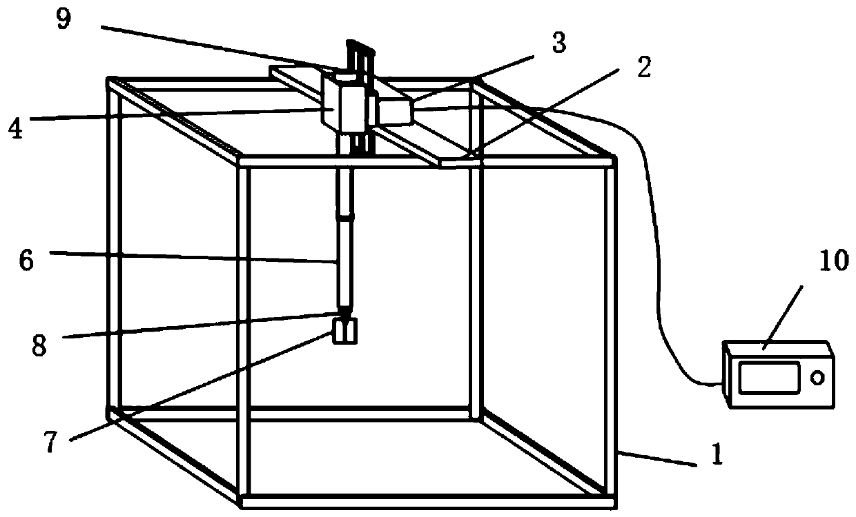
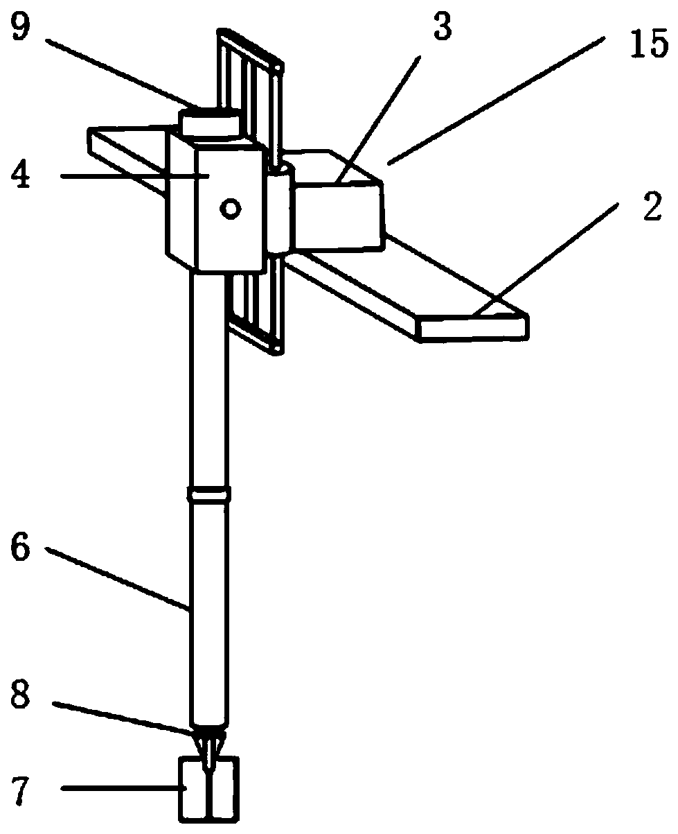
[0020] Such as figure 1 and figure 2 As shown, a kind of automatic cross-plate shearing instrument, described shearing instrument comprises host device 15 and described collection control device 10, and described host device comprises support frame 1, and described support frame 1 is rectangular parallelepiped frame, and frame is made of angle steel It is welded, the bottom surface and four sides of the support frame 1 are provided with plexiglass plates, a beam 2 is provided above the support frame 1, a lifting mechanism 3 is provided in the middle of the beam 2, and a lifting mechanism 3 is provided on the lifting mechanism 3. slide rail, the slide rail is placed vertically, and a torque output device 4 is provided on the slide rail, and the lifting ...


PUM

PropertyMeasurementUnit
diameteraaaaaaaaaa
lengthaaaaaaaaaa

Abstract

The invention provides an automatic vane shear apparatus. The shear apparatus comprises a main machine device, wherein the main machine device comprises a support frame; a cross beam is arranged abovethe support frame; a lifting mechanism is arranged on a middle part of the cross beam; a torsion output device is arranged on the lifting mechanism; a revolving shaft is arranged on a lower part of the torsion output device; a vane is arranged at upper and lower ends of the revolving shaft; and the revolving shaft is sleeved with a bushing. The automatic vane shear apparatus provided by the invention has the beneficial effects that the bushing is added to eliminate the frictional force and mechanical resistance torque of a soil body on a shaft lever, so that the test accuracy is improved; a vertical moving power mechanism is added to gradually press the vane into the soil body in a hydrostatic manner, so that vane shear test can be performed continuously on soil bodies at different depthswithout the need of opening holes in advance; and a multi-revolving-shaft connection manner is adopted, so that the test depth is increased.

Description

technical field [0001] The invention belongs to a device for in-situ testing of geotechnical engineering, and in particular relates to an automatic cross plate shearing instrument. Background technique [0002] In the field of geotechnical engineering investigation, in-situ cross-plate shear tests are usually used to determine the undrained shear strength of saturated soft clay, the undrained shear strength of reshaped soil and the sensitivity of soil. [0003] When using the cross-plate shearer to measure the undrained shear strength of the soil, the torsional moment is the sum of the torsional moment of the soil to the cross-plate head and the shaft. During the test, due to the friction and mechanical resistance of the soil on the shaft, the measured undrained shear strength is greater than the actual undrained shear strength of the soil, which affects the accuracy of the test parameters. The traditional cross-plate shearing instrument must be pre-drilled to a predetermin...

Claims


Application Information

Patent Timeline
Patent Type & Authority Applications(China)
IPC IPC(8): G01N3/24
CPCG01N3/24G01N2203/005
Inventor 韦实梁荣柱吴文兵方宇翔康成
Owner CHINA UNIV OF GEOSCIENCES (WUHAN)
Features
  • R&D
  • Intellectual Property
  • Life Sciences
  • Materials
  • Tech Scout
  • Unparalleled Data Quality
  • Higher Quality Content
  • 60% Fewer Hallucinations
Learn More