A stopper mechanism that effectively triggers micro switches and protects electrical components

A technology of micro-switches and electrical components, applied in electrical components, electrical switches, circuits, etc., can solve the problems of difficulty in effectively triggering the micro-switch parts 9, damage to the contacts of the micro-switch, and inability to trigger the action stroke, etc. Improve mean time to maintenance, trigger effectiveness and reliability, increase effectiveness and reliability

Active Publication Date: 2020-12-15
TIANJIN NAVIGATION INSTR RES INST
View PDF6 Cites 0 Cited by
  • Summary
  • Abstract
  • Description
  • Claims
  • Application Information

AI Technical Summary

Problems solved by technology

Although this solution solves the problem of damage to the torque motor and micro switch to a certain extent, it also has the following disadvantages in assembly and use: one is to realize the effective triggering of the micro switch part 9, that is, to satisfy the action of the micro switch part 9 Stroke range (the action stroke range of small size and precision micro switches is generally 0.3 ~ 0.6mm, and the trigger range is very narrow), the size H must be well controlled, and H is affected by the radius of rotation R of the internal frame 2 (usually can reach 200 ~300mm), the diameter Φ of the cylindrical stopper pin 7 and the contact extension dimension L when the micro switch 9 is actually triggered, it is very difficult to control the tolerance within the range of 0.3mm, and it is difficult to effectively trigger the micro switch 9. That is, if the action stroke is not enough, it cannot be triggered. If the action stroke is too large, the contact of the micro switch will be directly damaged; the second is that the trigger of the micro switch 9 is a lateral trigger, and the reliability of the trigger itself is poor.

Method used


Image

  • A stopper mechanism that effectively triggers micro switches and protects electrical components
  • A stopper mechanism that effectively triggers micro switches and protects electrical components
  • A stopper mechanism that effectively triggers micro switches and protects electrical components

Examples


Embodiment Construction

[0038]The embodiments of the present invention will be described in detail below in conjunction with the accompanying drawings. It should be noted that the embodiments are illustrative, not restrictive, and cannot limit the protection scope of the present invention.

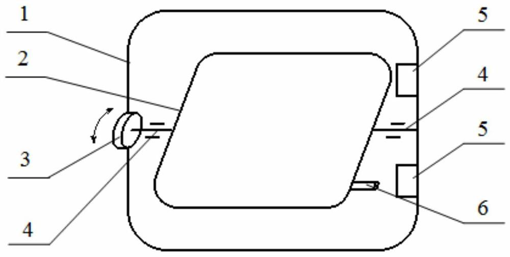
[0039] A stopper mechanism that effectively triggers micro switches and protects electrical components, including stopper pins and stoppers, combined below Figure 5 , Figure 6 and Figure 7 Detailed description of stop pins and stops:

[0040] ⑴. The stop pin is a cross-shaped trigger stop block in order to achieve effective trigger stop operation. The features of the parts are as follows: Figure 6 shown. This program requires that part 10 has a cross-shaped trigger stopper with upper and lower contact platforms to realize electrical triggering of one-way or two-way micro switches, such as Figure 6 Shown in 101 and 102. It is required that part 10 cross-shaped trigger stop block has left and right stop p...


PUM


Abstract

The invention relates to a stop mechanism for effectively triggering a microswitch and protecting an electrical element. The stop mechanism comprises a stop pin and a stop piece, wherein the stop pinis a cross-shaped triggering stop block, an upper contact table and a lower contact table are formed in the middle of the upper surface and the middle of the lower surface of the cross-shaped triggering stop block respectively, and a left stop table and a right stop table are arranged at the left side and the right side of the cross-shaped triggering stop block respectively; the stop piece comprises a segmented mechanical stop boss and the microswitch, a boss opening is formed in the center of the segmented mechanical stop boss, and a triggering convex head of the microswitch is located in theboss opening; and the cross-shaped triggering stop block, the segmented mechanical stop boss and the microswitch are installed on an internal framework and an external framework in a corresponding mode. According to the stop mechanism, through redesign of the characteristics and relative installation position of the stop mechanism, effective triggering of the microswitch is guaranteed, and effective stop between the rotary frameworks and effective protection of the electrical element are realized.

Description

technical field [0001] The invention relates to the technical field of inertial navigation frame rotation control, in particular to a stop mechanism for effectively triggering micro switches and protecting electrical components. Background technique [0002] Frame rotation is an important method for platform stabilization or error modulation of inertial navigation devices. For the signal transmission between the continuous rotating frames around the axis, it is usually realized by mechanical conductive slip rings, such as figure 1 As shown, the inner frame part 2 is driven by the torque motor part 3, and rotates in the outer frame part 1 around the rotating shaft part 4. At this time, the rotating shaft part 4 is equipped with a mechanical conductive slip ring, and the part 5 and Part 6 constitutes the stopper mechanism. [0003] However, mechanical conductive slip rings are expensive on the one hand, and reliability problems often occur due to rotating friction, which lea...

Claims


Application Information

Patent Timeline
Patent Type & Authority Patents(China)
IPC IPC(8): H01H13/18
CPCH01H13/18
Inventor 杨盛林于洪宇王晓丹张宇
Owner TIANJIN NAVIGATION INSTR RES INST
Why Eureka
Try Eureka