Electric driving system and copper bar oil cooling structure thereof

An electric drive system and oil cooling technology, applied in the direction of electric components, electrical components, electromechanical devices, etc., can solve the problems of heat generation at the connection position of copper bars, failure of components, etc., and achieve the goal of avoiding excessive temperature, low difficulty, and uniform cooling Effect

Active Publication Date: 2022-01-11
LEADRIVE TECH (SHANGHAI) CO LTD
View PDF5 Cites 0 Cited by
  • Summary
  • Abstract
  • Description
  • Claims
  • Application Information

AI Technical Summary

Problems solved by technology

When the bridge continues to work with high torque, the connection position of the copper bar continues to heat up, which leads to the risk of failure of components in the cavity

Method used


Image

  • Electric driving system and copper bar oil cooling structure thereof
  • Electric driving system and copper bar oil cooling structure thereof
  • Electric driving system and copper bar oil cooling structure thereof

Examples


Embodiment Construction

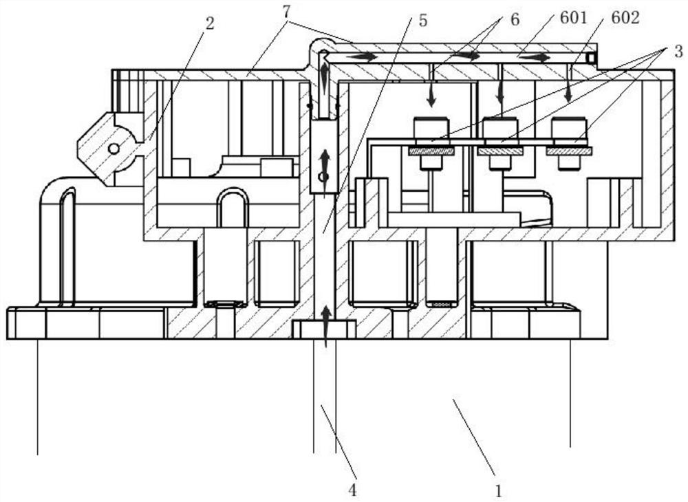
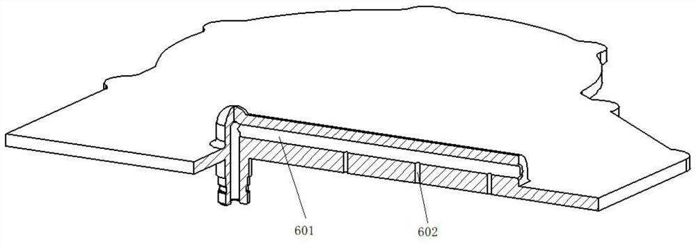
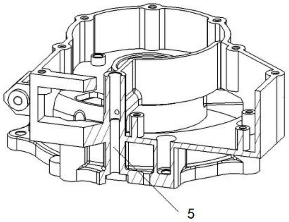
[0022] The advantages of the present invention will be further elaborated below in conjunction with the accompanying drawings and specific embodiments.

[0023] Reference will now be made in detail to the exemplary embodiments, examples of which are illustrated in the accompanying drawings. When the following description refers to the accompanying drawings, the same numerals in different drawings refer to the same or similar elements unless otherwise indicated. The implementations described in the following exemplary examples do not represent all implementations consistent with the present disclosure. Rather, they are merely examples of apparatuses and methods consistent with aspects of the present disclosure as recited in the appended claims.

[0024] The terminology used in the present disclosure is for the purpose of describing particular embodiments only, and is not intended to limit the present disclosure. As used in this disclosure and the appended claims, the singular...


PUM


Abstract

The invention provides a copper bar oil cooling structure of an electric driving system, the electric driving system comprises a motor and a controller, the motor is arranged in a shell, one end of the shell is provided with an end cover, and one side, opposite to the motor, of the end cover is connected with a cover plate; an electric connecting piece for connecting the motor and the controller is arranged in the end cover; a first oil guide path is arranged on the shell, a second oil guide path is arranged in the cover plate, and an axial drainage path is arranged between the first oil guide path and the second oil guide path; one end of the first oil guide path is communicated with an oil guide source, and the other end of the first oil guide path is communicated with the drainage oil path; and one end of the second oil guide way is communicated with the drainage oil way, and the other end of the second oil guide way is arranged corresponding to the electric connecting piece, so that cooling oil in the oil guide source flows to the second oil guide way to spray and cool the electric connecting piece.

Description

technical field [0001] The invention relates to the technical field of electric drive systems, in particular to an electric drive system and a copper row oil cooling structure of the electric drive system. Background technique [0002] In the bridge system, the controller and the motor are connected to each other through the copper bar to realize the conduction of current, and the connection position of the copper bar is due to the existence of contact resistance, so the temperature will rise when a large current passes through. When the bridge continues to work with high torque, the connection position of the copper bar continues to heat up, which leads to the risk of failure of components in the cavity. In the prior art, the active cooling of the insulating block can take away the heat at the connection position of the copper bar in time to avoid the occurrence of failure. Contents of the invention [0003] In order to overcome the above-mentioned technical defects, the...

Claims


Application Information

Patent Timeline
IPC IPC(8): H02K5/20H02K9/19
CPCH02K5/203H02K9/19
Inventor 沈捷
Owner LEADRIVE TECH (SHANGHAI) CO LTD
Why Eureka
Try Eureka