Check patentability & draft patents in minutes with Patsnap Eureka AI!

Hydraulic robot

A technology of hydraulic robots and hydraulic cylinders, applied in the directions of manipulators, program-controlled manipulators, manufacturing tools, etc., to achieve the effect of avoiding torsion and improving the strength of force application

Pending Publication Date: 2019-07-26
安徽奥博智能科技有限公司
View PDF0 Cites 1 Cited by
  • Summary
  • Abstract
  • Description
  • Claims
  • Application Information

AI Technical Summary

Problems solved by technology

[0002] With the development of science and technology, the application of robots in production and processing is becoming more and more common. However, the existing robots still have shortcomings in terms of stability, load-bearing capacity and force-exerting capacity during work, which need to be improved urgently.

Method used


Image

  • Hydraulic robot

Examples


Embodiment Construction

[0018] Hereinafter, the technical solution of the present invention will be described in detail through specific embodiments.

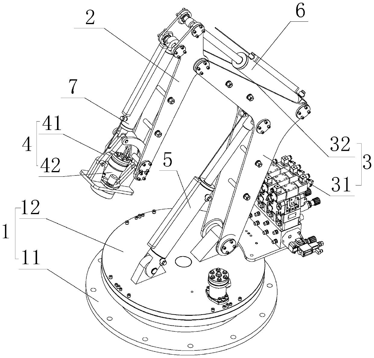
[0019] Such as figure 1 As shown, figure 1 It is a schematic structural diagram of a hydraulic robot proposed by the present invention.

[0020] Reference figure 1 , A hydraulic robot proposed by the present invention includes: a base 1, a secondary movable arm 2, a main movable arm 3 and a hydraulic system, wherein:

[0021] One end of the auxiliary movable arm 2 is movably installed with a mounting seat 4 for installing the mounting seat; the end of the auxiliary movable arm 2 away from the mounting seat 4 is provided with a first connection point and a second connection point along its length, and the first connection point It is located on the side of the second connection point close to the mounting base 4; one end of the main movable arm 3 is movably connected with the base 1, and the end of the main movable arm 3 away from the base 1 is movably con...


PUM


Abstract

The invention discloses a hydraulic robot which comprises a base, an auxiliary movable arm, a main movable arm and a hydraulic system. One end of the auxiliary movable arm is movably provide with a mounting seat, and the other end of the auxiliary movable arm is provided with a first connecting point and a second connecting point. One end of the main movable arm is connected with the base, and theother end of the main movable arm is connected with the first connecting point of the auxiliary movable arm. The hydraulic system comprises a first hydraulic cylinder, a second hydraulic cylinder anda third hydraulic cylinder. The ejection end of a piston rod in the first hydraulic cylinder is connected with the main movable arm, and the end, far away from the ejection end of the piston rod, ofthe first hydraulic cylinder is connected with the base. The ejection end of a piston rod in the second hydraulic cylinder is connected with the second connecting point of the auxiliary movable arm, and the end, far away from the ejection end of the piston rod, of the second hydraulic cylinder is connected with the main movable arm. The ejection end of a piston rod in the third hydraulic cylinderis movably connected with the mounting base, and the end, far away from the ejection end of the piston rod, of the third hydraulic cylinder is connected with the auxiliary movable arm. The hydraulic robot is stable in structure and strong in load and force application capacity.

Description

Technical field [0001] The invention relates to the technical field of processing equipment, in particular to a hydraulic robot. Background technique [0002] With the development of science and technology, the application of robots in production and processing has become more and more common. However, the existing robots still have shortcomings in the stability, load-bearing capacity and force application ability of the existing robots, and urgent improvement is needed. Summary of the invention [0003] Based on the technical problems existing in the above background art, the present invention proposes a hydraulic robot. [0004] The hydraulic robot proposed by the present invention includes: a base, a secondary movable arm, a main movable arm and a hydraulic system, wherein: [0005] One end of the auxiliary movable arm is movably installed with a mounting seat for installing the mounting seat; the end of the auxiliary movable arm away from the mounting seat is provided with a firs...

Claims


Application Information

Patent Timeline
Patent Type & Authority Applications(China)
IPC IPC(8): B25J9/00
CPCB25J9/00
Inventor 邓志威郑玉国唐云双
Owner 安徽奥博智能科技有限公司
Features
  • R&D
  • Intellectual Property
  • Life Sciences
  • Materials
  • Tech Scout
  • Unparalleled Data Quality
  • Higher Quality Content
  • 60% Fewer Hallucinations
Learn More