Anti-explosion electric control lock body capable of detecting illegal valve opening for oil tank truck API valve
An oil tanker and electric control lock technology, applied in the field of oil tanker valves, can solve the problems of inability to prevent violent disassembly, large daily consumption of lead seals, consumption of electronic lead seals, etc., to increase the difficulty of theft and increase the difficulty of applying force The effect of increasing the difficulty of operation
- Summary
- Abstract
- Description
- Claims
- Application Information
AI Technical Summary
Problems solved by technology
Method used
Image

Examples
Embodiment 1
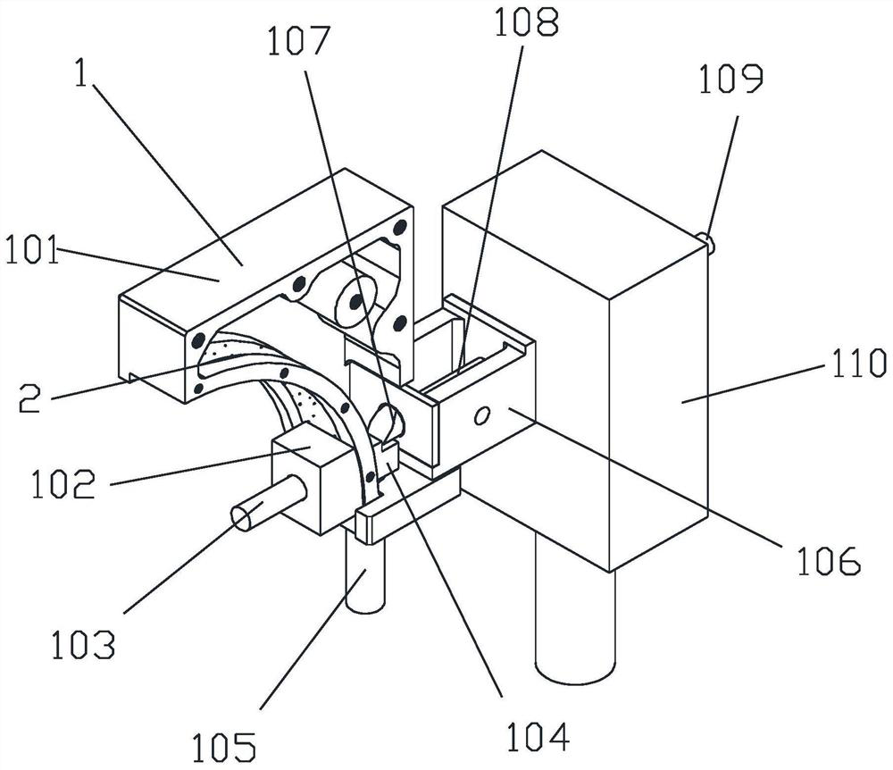
[0029] Such as Figure 1-2 As shown, the present invention provides a technical solution: an explosion-proof electronically controlled lock body for an API valve of an oil tanker that can detect illegal valve opening, including a main body module 1, and the main body module 1 includes a lock body part and a lock part , the API valve is locked on the lock body through a lock;
[0030] The lock body includes a lock box 101, a pin slider 102, a connecting pin 103 and a lock block 104, the inside of the lock box 101 is hollow, and the front end of the lock box 101 is provided with a pin slider 102, the API valve is connected to each other through the connecting pin 103 and the pin slider 102, by controlling the connecting pin 103 between the valve stem and the rotating shaft, so as to control whether the valve is allowed to open, the corresponding pin inside the lock box 101 The position of the slider 102 is provided with a lock block 104, and the pin slider 102 and the lock bloc...
Embodiment 2
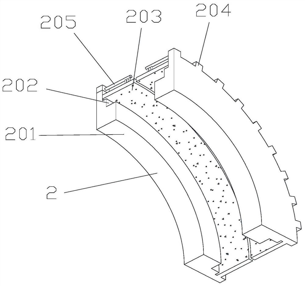
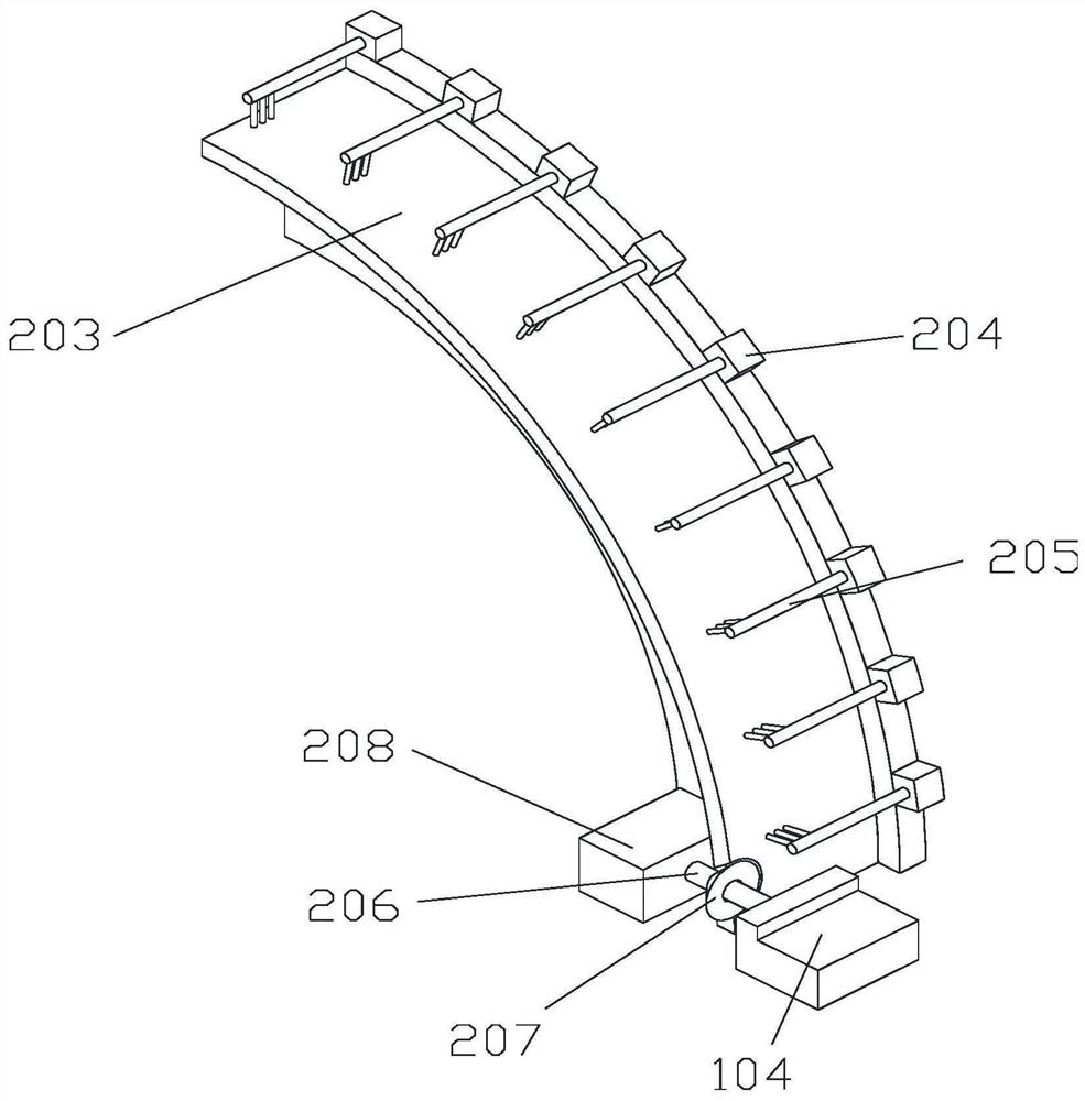
[0038] On the basis of Example 1, as Figure 2-3 Shown:
[0039] The track baffles 203 are two groups of arc-shaped plates, and the two groups of track baffles 203 are arranged at intervals;
[0040] Described connector comprises connecting rod 206, restriction cone 207 and rail slide block 208, and described rail slide block 208 is arranged on the inside of moving track on slideway main body 201, and track slide block 208 and pin slide block 102 are fixedly connected with each other, so The track slider 208 and the lock block 104 are fixedly connected to each other through the connecting rod 206, and the conical restricting cone 207 is movably installed on the connecting rod 206, and the restricting cone 207 can rotate on the connecting rod 206, and the restricting cone 207 can move between two groups of track baffles 203 and make the track baffles 203 at corresponding positions curl up,
[0041] The adjustment module 2 also includes an adapter slot 202, a fixing block 204 ...
Embodiment 3
[0044] On the basis of Example 1, as Figure 4 Shown:
[0045] The track baffle 203 is an arc-shaped plate protruding outward from above, and the track baffle 203 is installed in the moving track of the slideway main body 201;
[0046] Described connector comprises rail slider 208, and described rail slider 208 is arranged between pin slider 102 and lock block 104, and pin slider 102 and lock block 104 are mutually fixedly connected by rail slider 208, and track The bottom of the baffle plate 203 is fixedly installed on the rail slider 208, and the rail slider 208 moves in the moving track of the slideway main body 201 so that the rail baffle plate 203 is deformed for adaptation;
[0047] The adjustment module 2 also includes an adjustment base block 209, an adjustment groove 210, an adjustment ball 211, a restriction block 212 and a restriction spring 213. The adjustment base block 209 is fixedly installed on the inner top of the lock box 101, and the position of the adjustm...
PUM
 Abstract
Description
Claims
Application Information