Rotary Masterbatch Cooling Device

A technology of cooling device and color masterbatch, which is applied in the direction of coating, etc., can solve problems such as the need to improve efficiency, and achieve the effects of avoiding long-term stacking contact, improving cooling effect, and alleviating adhesion

Active Publication Date: 2021-02-05
TIANJIN YISANYOU MASTERBATCH CO LTD
View PDF3 Cites 0 Cited by
  • Summary
  • Abstract
  • Description
  • Claims
  • Application Information

AI Technical Summary

Problems solved by technology

[0004] The purpose of the present invention is to address the technical defects of the prior art and provide a rotary masterbatch cooling device to solve the technical problem that the efficiency of conventional cooling methods needs to be improved in the prior art

Method used


Image

  • Rotary Masterbatch Cooling Device
  • Rotary Masterbatch Cooling Device
  • Rotary Masterbatch Cooling Device

Examples


Embodiment 1

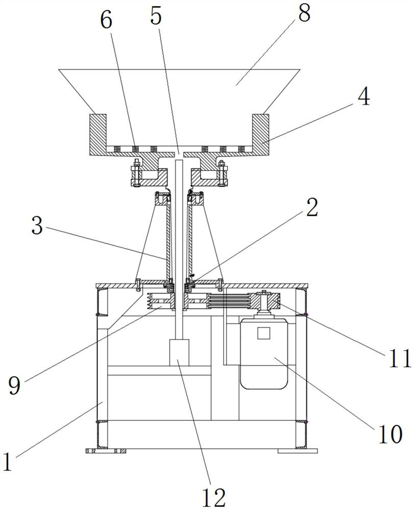
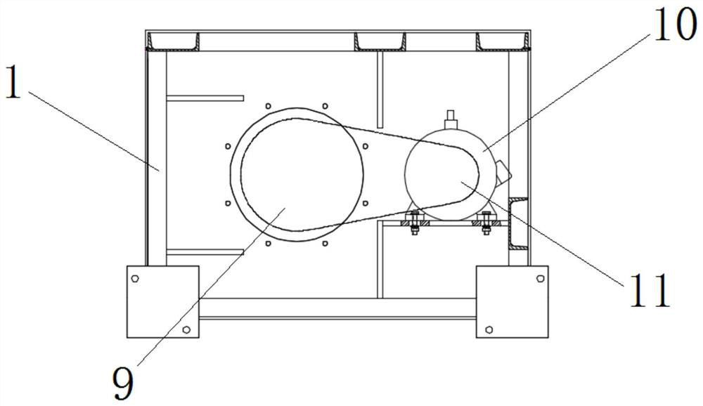
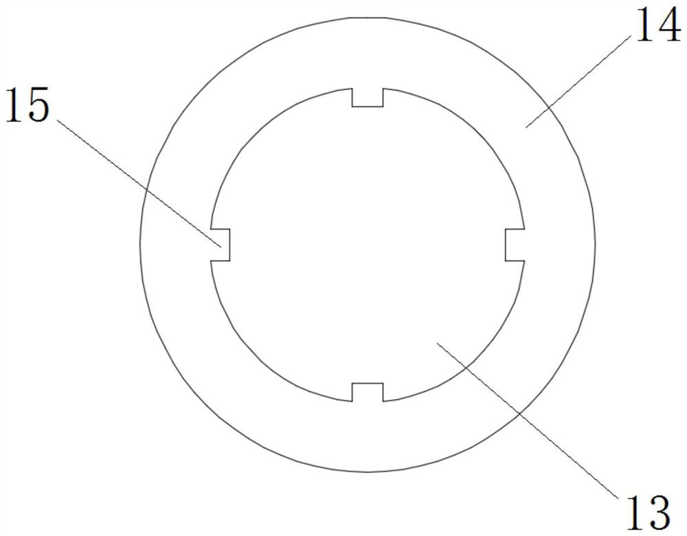
[0025] Rotary masterbatch cooling device, such as Figure 1~4 As shown, it includes box body 1, bearing 2, hollow shaft 3, cylinder body 4, through hole 5, spring 6, convex strip 7, container 8, driven gear 9, motor 10, driving gear 11, electric push rod 12, Cylindrical part 13, wide mouth part 14, strip groove 15, wherein box body 1 has an inner chamber, is connected with bearing 2 on the upper end of described box body 1, is connected with hollow shaft 3 on described bearing 2, so The axis of the hollow shaft 3 is vertical, and a cylinder 4 is fixedly connected to the top end of the hollow shaft 3, and a through hole 5 is opened in the center of the bottom surface of the cylinder 4, and the top end of the bottom surface of the cylinder 4 is fixedly connected to There are some springs 6, and some convex strips 7 are fixedly connected on the inner wall of the cylinder body 4; the container 8 includes a cylindrical portion 13 and a wide-mouth portion 14, and the wide-mouth port...

Embodiment 2

[0028] Rotary masterbatch cooling device, such as Figure 1~4As shown, it includes box body 1, bearing 2, hollow shaft 3, cylinder body 4, through hole 5, spring 6, convex strip 7, container 8, driven gear 9, motor 10, driving gear 11, electric push rod 12, Cylindrical part 13, wide mouth part 14, strip groove 15, wherein box body 1 has an inner chamber, is connected with bearing 2 on the upper end of described box body 1, is connected with hollow shaft 3 on described bearing 2, so The axis of the hollow shaft 3 is vertical, and a cylinder 4 is fixedly connected to the top end of the hollow shaft 3, and a through hole 5 is opened in the center of the bottom surface of the cylinder 4, and the top end of the bottom surface of the cylinder 4 is fixedly connected to There are some springs 6, and some convex strips 7 are fixedly connected on the inner wall of the cylinder body 4; the container 8 includes a cylindrical portion 13 and a wide-mouth portion 14, and the wide-mouth porti...


PUM


Abstract

The invention provides a rotary color masterbatch cooling device. In this technical solution, the color masterbatch is carried in the container, and the container is plugged into the inside of the cylinder, so that the convex line on the inner wall of the cylinder and the strip groove on the side wall of the container form a transmission relationship. On this basis, the motor and gears are used to drive the hollow The shaft rotates, and then drives the cylinder and the container to rotate. Based on the rotation of the container, the air flow rate around the masterbatch can be increased, which helps to improve the cooling effect; Repeatedly impact the bottom of the container, so that the color masterbatch in it is continuously thrown up and dispersed during the rotation process, thereby significantly increasing the heat exchange area between the color masterbatch and the external environment, and has a better cooling effect. In addition, the oscillating throwing mode of the present invention can avoid long-term stacking and contact of the color masterbatches, thereby alleviating the adhesion phenomenon of the color masterbatches during the cooling process.

Description

technical field [0001] The invention relates to the technical field of color masterbatch production equipment, in particular to a rotary color masterbatch cooling device. Background technique [0002] Color masterbatch, also known as color masterbatch, is also called color seed. It is a new type of special colorant for polymer materials, also known as pigment preparation. Color masterbatches are mainly used in plastics. The color masterbatch is composed of three basic elements: pigment or dye, carrier and additive. It is an aggregate made by uniformly loading super-normal pigments in the resin. It can be called a pigment concentrate, so its coloring power is higher than that of the pigment itself. When processing, a small amount of color masterbatch and uncolored resin is mixed to achieve the colored resin or product with the designed pigment concentration. [0003] In the process of masterbatch processing, the prepared mixture is first made into strips, and then cut into...

Claims


Application Information

Patent Timeline
Patent Type & Authority Patents(China)
IPC IPC(8): B29B9/06B29B9/16B29B13/04
CPCB29B9/06B29B9/16B29B13/045
Inventor 国旺
Owner TIANJIN YISANYOU MASTERBATCH CO LTD
Why Eureka
Try Eureka