
Injection molding mold

An injection mold and injection molding technology, applied in the field of molds, can solve the problems of injection runner impact, poor edge molding effect of plastic parts, uneven material flow rate, etc., and achieve the effects of slowing the impact, improving product quality, and reasonable material distribution.

Inactive Publication Date: 2019-07-26
陈孙立
View PDF5 Cites 2 Cited by
  • Summary
  • Abstract
  • Description
  • Claims
  • Application Information

AI Technical Summary

Problems solved by technology

[0003] In the prior art, when the material is injected into the injection main channel by high pressure, the material flow rate is uneven, which will have a certain impact on the injection runner, resulting in poor edge molding effect of the finished plastic part

Method used


Image

  • Injection molding mold
  • Injection molding mold

Examples


Embodiment Construction

[0014] Below in conjunction with accompanying drawing and embodiment the invention will be further described:

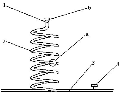
[0015] Such as figure 1 with figure 2 As shown, an injection mold includes a pouring system, and the pouring system includes an injection main channel and an injection runner, the injection runner communicates with the cavity, the injection main channel is a spiral runner, and the port of the injection main channel is Inverted cone shape, with screw valve on the injection runner.

[0016] In this embodiment, the axis of the main injection channel is perpendicular to the axial direction of the injection runner, and the connection between the injection main channel and the injection runner is arc-shaped.

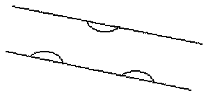
[0017] In this embodiment, protrusions are evenly distributed on the inner wall of the main injection channel, and the screw valve and the injection branch channel are fixed by threads. The screw valve is used to control the plastic flow rate of the sub-runner, s...


PUM


Abstract

The invention discloses an injection molding mold. The injection molding mold comprises a casting system. The casting system comprises an injection molding main runner and injection molding sub runners. The injection molding sub runners communicate with a molding cavity. The injection molding mold is structurally characterized in that the injection molding main runner is a spiral type runner; theport of the injection molding main runner is of an inverted-cone shape; and screw valves are arranged in the injection molding sub runners. The injection molding mold has the beneficial effects that the structure is simple, and the design is reasonable. The injection molding main runner is designed to be a spiral shape, the joint of the injection molding main runner and the injection molding sub runners are arranged to be an arc shape, and impact on the injection molding sub runners by materials injected through high pressure can be effectively slowed down. Bulges uniformly distributed on theinner wall of the injection molding main runner also have certain flow-slowing effect. The inverted-cone shape is adopted by the port of the injection molding main runner and can play a pressurizing part so that the flow velocity of the materials is more powerful and steadier. A screw valve is arranged in each injection molding sub runner and used for controlling the injection molding flow of eachinjection molding sub runner so that material distribution inside the molding cavity can be reasonable and the product quality can be improved.

Description

technical field [0001] The invention relates to the field of molds, in particular to an injection mold. Background technique [0002] An injection mold is a type of mold used when the injection molding method is used. Injection molding refers to the method in which heated and melted materials are injected into the mold cavity by high pressure, and after cooling and solidification, molded products are obtained. Injection mold refers to a device in which resin material is injected into a metal model to obtain a product with a certain shape. [0003] In the prior art, when the material is injected into the injection molding main channel by high pressure, the material flow rate is uneven, which will have a certain impact on the injection molding runner, resulting in poor edge molding effect of the finished plastic part. Contents of the invention [0004] In order to solve the above technical problems, the present invention provides an injection mold, which can slow down the ...

Claims


Application Information

Patent Timeline
Patent Type & Authority Applications(China)
IPC IPC(8): B29C45/27B29C45/30
CPCB29C45/27B29C45/30
Inventor 陈孙立
Owner 陈孙立
Learn More