Detection structure and image molding device

An image forming and detection technology, which is applied to printing devices, typewriters, printing, etc., can solve the problems of complex paper position information detection structure, etc., and achieve the effect of reducing the number of structures, simple installation and matching structure, and cost reduction

Active Publication Date: 2019-07-26
联想图像(山东)科技有限公司
View PDF9 Cites 1 Cited by
  • Summary
  • Abstract
  • Description
  • Claims
  • Application Information

AI Technical Summary

Problems solved by technology

[0005] Therefore, the technical problem to be solved by the present invention is to overcome the defect of the complex detection structure of the pape

Method used


Image

  • Detection structure and image molding device
  • Detection structure and image molding device
  • Detection structure and image molding device

Examples


Embodiment 1

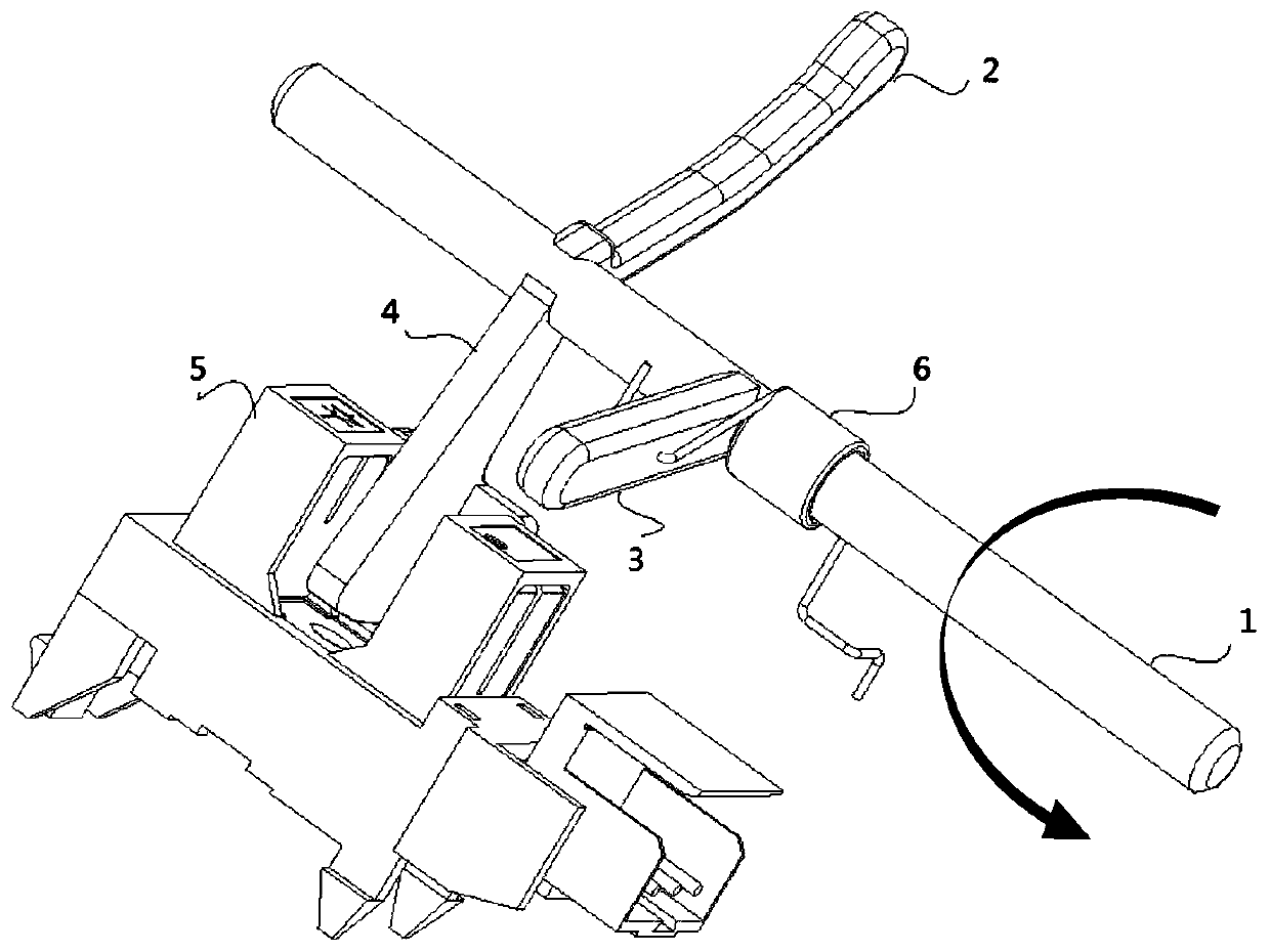
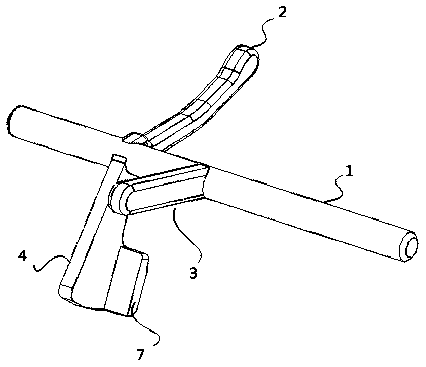
[0050] Such as figure 1As shown in -3, a detection structure provided for this embodiment includes a central axis 1, which is rotatably arranged on a paper board; a first detection arm 2 and a second detection arm 3, which are arranged at an angle On the peripheral surface of the central axis 1, and can be respectively arranged in the front printing path and the reverse printing path; the trigger arm 4, one end is arranged on the peripheral surface of the rotating shaft 1, and one end is correspondingly arranged with the sensing area of ​​the sensor 5, printing The medium triggers the first detection arm 2 and the second detection arm 3 respectively in the front printing path and the reverse printing path, and drives the trigger arm 4 to rotate to realize the triggering of the sensor 5; the reset structure 6 is arranged on the central axis 1 , used to drive the axis 1 to rotate, and drive the trigger arm 4 to reset to a position not triggered by the printing medium.

[0051] ...

Embodiment 2

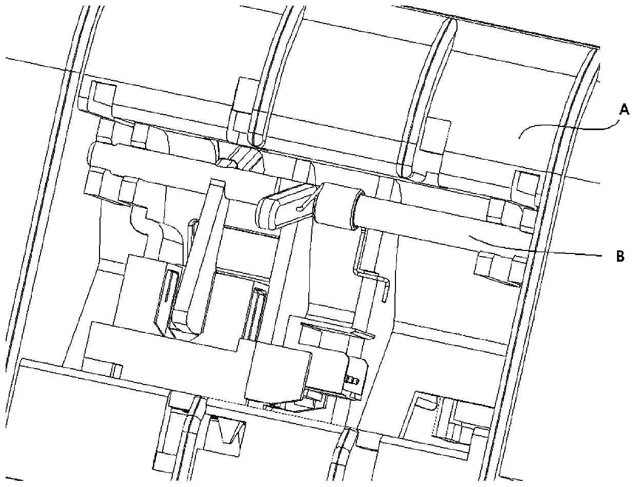
[0068] Such as Figure 4 As shown, an image forming device provided in this embodiment includes the detection structure described in Embodiment 1 above, and has all its technical advantages. Its working process is as follows:

[0069] The printing medium d coming out of the pick-up roller 8 enters the front printing channel e, and the head of the printing medium d triggers the detection structure in Embodiment 1, and finally hits it from position a to position c through position b to realize After the triggering of the sensor, the printing medium d enters the printing channel f on the reverse side, and before the head of the printing medium d touches the detection structure again, its tail end breaks away from the detection structure, and then repeats the printing detection on the front side process, and finally complete the detection of the position of the front and back printing media.


PUM


Abstract

The invention provides a detection structure and an image molding device. The detection structure comprises a central shaft, a first detection arm, a second detection arm, a trigger arm, and a resetting structure, wherein the central shaft is rotatably arranged on a paper circuit board; the first detection arm and the second detection arm are arranged on the circumferential face of a rotating shaft in an angle mode and capable of being respectively arranged on a font printing through path and a back printing through path; one end of the trigger arm is arranged on the circumferential face of the rotating shaft, the other end of the trigger arm corresponds to a sensing area of a sensor, and a printing medium triggers the first detection arm and the second detection arm in the font printing through path and the back printing through path to drive the trigger arm to rotate so as to achieve the trigger of the sensor; and the resetting structure is arranged on the central shaft and used fordriving the central shaft to rotate to drive the trigger arm to be reset to the un-triggered position by the printing medium. The detection structure is simple in whole structure and low in cost.

Description

technical field [0001] The invention relates to the technical field of printers, in particular to a detection structure and an image forming device. Background technique [0002] Printers are widely used as devices that realize image formation on related media. With the progress of the times, due to the saving of resources such as paper, printers capable of printing on both sides of paper have been developed. [0003] However, in the existing double-sided printers, the printing on the front side of the paper and the printing on the back side require different paper feeding channels. A sensor for detection of front printing and a sensor for detection of reverse printing arranged at the entrance of reverse printing are arranged at the paper opening. [0004] The above-mentioned detection structure requires two sets of sensors and the design of an installation structure corresponding to the sensors on the paper path, and the structure is relatively complicated and the cost is...

Claims


Application Information

Patent Timeline
IPC IPC(8): B41J11/00B41J3/60
CPCB41J3/60B41J11/0095
Inventor 陈雄
Owner 联想图像(山东)科技有限公司
Why Eureka
Try Eureka