
Loom spindle balance block structure

A technology of balance weight and main shaft, which is applied in looms, textiles, textiles and papermaking, etc. It can solve the problems of vibrating fabric quality, rotation loss of balance, and affecting looms, so as to improve weaving quality and efficiency, weaken inertial force, and facilitate Adjustment effect

Pending Publication Date: 2019-07-26
SHANDONG RIFA TEXTILE MACHINERY
View PDF5 Cites 0 Cited by
  • Summary
  • Abstract
  • Description
  • Claims
  • Application Information

AI Technical Summary

Problems solved by technology

[0002] The rotation of the main shaft of the loom drives the weft beating and weft insertion movements of the loom. The stability of the main shaft directly affects the performance of the loom, and also has a great impact on the quality of the fabric; the unstable operation of the main shaft will cause loud noise, Severe vibration, many fabric defects, etc.
[0003] When the loom is beating up, the main shaft needs to provide a large reed swing force to the beating mechanism to overcome the beating resistance of the warp and weft yarns, so that the weft yarns can be driven into the weaving mouth. Therefore, when the main shaft of the loom rotates to the beating position, the steel When the reed swings and beats up the weft, the main shaft will be subjected to a force opposite to the actual rotation direction, thus losing balance, causing the main shaft to rotate unstable, causing the loom to vibrate and the reed to vibrate, resulting in fabric quality defects
[0004] Additionally, if figure 1 As shown, when the main shaft of the loom rotates at high speed to drive the weft insertion mechanism to reciprocate, because the traditional structure drives the weft insertion moving bracket of the weft insertion mechanism to reciprocate through the crank and connecting rod, and when the weft insertion mechanism reciprocates, its inertia The force will cause the spindle to be subjected to a force opposite to the actual rotation direction, and the rotation will easily lose balance, resulting in unstable rotation of the spindle.

Method used


Image

  • Loom spindle balance block structure
  • Loom spindle balance block structure
  • Loom spindle balance block structure

Examples


Embodiment Construction

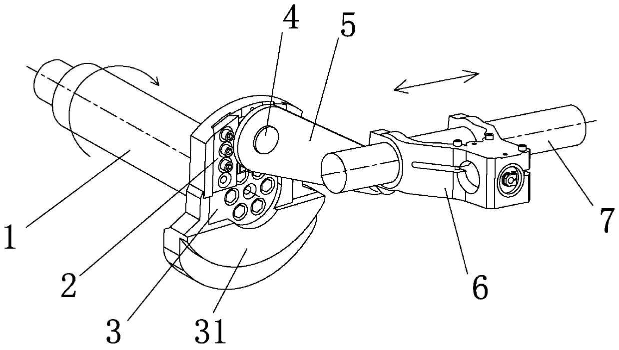
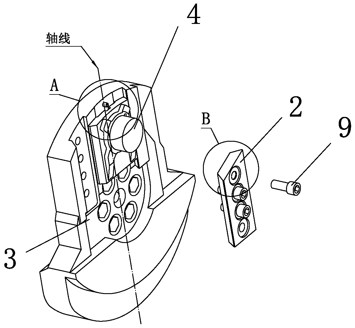
[0027] Such as figure 1 As shown, a main shaft balance weight structure of a loom includes a main shaft 1 and weft insertion mechanisms located at two ends of the main shaft 1 . Balance weights 3 are respectively fixedly arranged on the end faces of the two ends of the main shaft 1 , and the middle part of the main shaft 1 is fixedly connected with the balance weight 3 .

[0028] As a specific implementation, the balance weight 3 described in this embodiment is fixedly connected to the main shaft 1 through screws 9 .

[0029] One end of the balance weight 3 is a counterweight 31 , the other end of the balance weight 3 is hinged to one end of the connecting rod 5 , and the other end of the connecting rod 5 is hinged to the weft insertion moving bracket 6 . The moving bracket 6 for weft insertion is arranged on the guide shaft 7 and can drive the weft insertion mechanism to reciprocate along the guide shaft 7 .

[0030] This patent does not involve the specific internal struct...


PUM


Abstract

The invention discloses a loom spindle balance block structure, and relates to the technical field of textile machinery. The structure comprises a spindle, balance blocks are fixedly arranged on two sides of a spindle, one end of each balance block is a balance weight portion, the other end of the balance block is connected with a weft insertion movable support through a connecting rod, and two ends of each connecting rod are rotatably connected with the corresponding balance block and the corresponding weft insertion movable support. Weft insertion adjusting sliders rotatably connected with the connecting rods are arranged among the connecting rods and the balance blocks and have a plurality of mounting positions on the balance blocks. In order to facilitate adjustment, a sliding groove for containing the corresponding weft insertion adjusting slider is formed in each balance block, and the weft insertion adjusting sliders are fixedly locked with the balance blocks through pressing blocks. The balance blocks are mounted on the spindle, the problem of imbalance rotation of the spindle is solved, loom vibration is relieved, loom noise is reduced, and the woven quality of a fabric isimproved.

Description

technical field [0001] The invention relates to the technical field of textile machinery, in particular to a balance weight structure of a main shaft of a loom. Background technique [0002] The rotation of the main shaft of the loom drives the weft beating and weft insertion movements of the loom. The stability of the main shaft directly affects the performance of the loom, and also has a great impact on the quality of the fabric; the unstable operation of the main shaft will cause loud noise, Severe vibration, many fabric defects, etc. [0003] When the loom is beating up, the main shaft needs to provide a large reed swing force to the beating mechanism to overcome the beating resistance of the warp and weft yarns, so that the weft yarns can be driven into the weaving mouth. Therefore, when the main shaft of the loom rotates to the beating position, the steel When the reed swings and beats up the weft, the main shaft will be subjected to a force opposite to the actual rot...

Claims


Application Information

Patent Timeline
Patent Type & Authority Applications(China)
IPC IPC(8): D03D51/00D03D49/60D03D49/50D03D47/00
CPCD03D51/00D03D49/60D03D49/50D03D47/00
Inventor 宋长杰迟连迅董天刚
Owner SHANDONG RIFA TEXTILE MACHINERY
Learn More