Acoustic anisotropic reverse-time migration mixing method
An anisotropic and reverse time migration technology, applied in the field of acoustic wave anisotropy reverse time migration mixing and acoustic reverse time migration, it can solve problems such as low computational efficiency, and achieve the goal of improving computational efficiency, improving computational efficiency, reducing The effect of computing memory requirements
Active Publication Date: 2019-07-26
JILIN UNIV
View PDF3 Cites 7 Cited by
- Summary
- Abstract
- Description
- Claims
- Application Information
AI Technical Summary
Benefits of technology
This patented new technique described in this patents allows us to efficiently compute sound waves from different directions while reducing computational complexity compared to existing methods like pseudospectric analysis (PCA). It involves solving inverse Time Migration Problem(ITM) through both traditional and improved algorithms called Acoustoan Imaging Method (AIM), Anomalous Wave Theory (AWT), Duality Interference Finite Layer Transform (DIFT) algorithm, Computational Fluid Dynamics (CFD)-based techniques such as Direct Simultaneous Rotary Squamatic Tensor Network (RSSTN)). These improvements make calculations easier than current methods due to their ability to handle complex geology structures without requiring expensive equipment.
Problems solved by technology
This patent discusses different ways how crude oils can form overseas deposit zones where they may enter deeper sea areas or near shore locations. These deposited materials include sands, shale layers, boreshaped wellbons, submarine sedimentary basins, etc., which pose technical challenge because traditional techniques require significant computing power and involve complicated mathematical operations. Acoustic inverse travel technique provides efficient solution but faces issues related to computational efficiency and processing speed.
Method used
View moreImage
Smart ImageViewing Examples
Examples
Embodiment 1
[0081] According to the specific hardware environment, choose to install the OpenMP compilation library under the Linux system and complete the construction of the GCC compilation platform.
Login to View More PUM
 Abstract
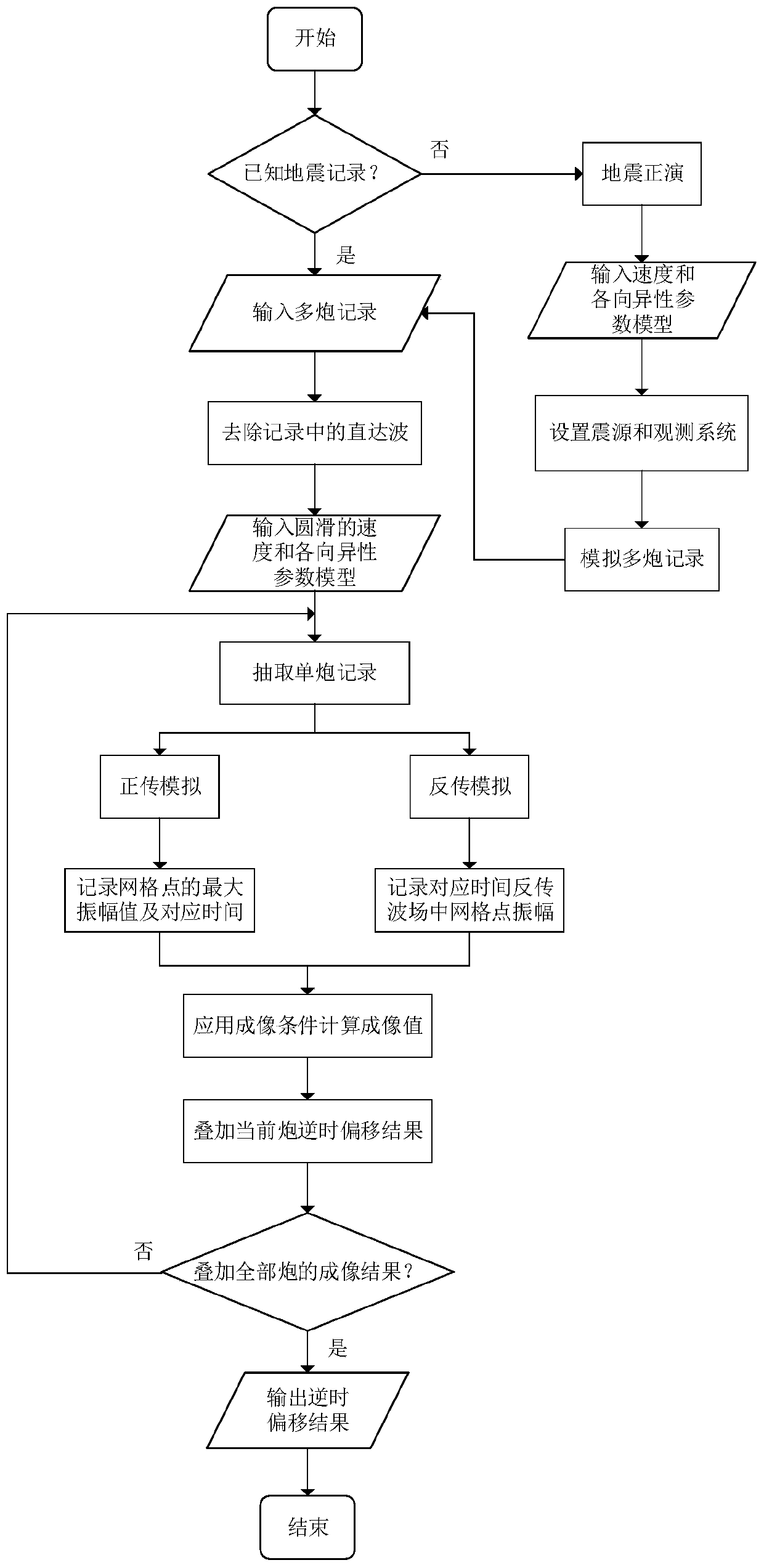
The invention relates to an acoustic anisotropic reverse-time migration mixing method. A reverse-time migration imaging process is divided into the following steps: 1, setting an observation system and a seismic source location when no seismic data is input to obtain seismic data in anisotropic media, and solving an anisotropic acoustic wave equation by a mixed pseudo-spectral method and an finitedifference method, wherein during application of the finite difference method, high-order rotating staggered grids are adopted to ensure the calculation accuracy and stability, and only one fast Fourier transform is needed at each time step; and 2, applying an improved excitation amplitude imaging condition according to the input seismic data to perform inverse-time migration imaging. The forwardseismic transmission process and the reverse seismic record transmission process are carried out based on the above algorithm, and then reverse-time migration imaging is carried out. The need for computational memory is reduced in a wide range of computational areas. The calculation efficiency of reverse-time migration is improved, seismic acoustic recording is simulated in a large scale of complex anisotropic media, and reverse-time migration imaging is performed.
Description
Login to View More Claims
Login to View More Application Information
Patent Timeline
 Owner JILIN UNIV
Features
- R&D
- Intellectual Property
- Life Sciences
- Materials
- Tech Scout
- Unparalleled Data Quality
- Higher Quality Content
- 60% Fewer Hallucinations
Learn More Browse by: Latest US Patents, China's latest patents, Technical Efficacy Thesaurus, Application Domain, Technology Topic, Popular Technical Reports.
© 2025 PatSnap. All rights reserved.Legal|Privacy policy|Modern Slavery Act Transparency Statement|Sitemap|About US| Contact US: help@patsnap.com


