Synergistic pulse signal generator

A pulse signal and generating device technology, applied in pulse duration/width modulation, medical science, surgery, etc., can solve problems such as high cost of use, incomplete tumor ablation, complex structure, etc., achieve low manufacturing and use costs, overcome The problem of tumor heterogeneity and the effect of simple device structure

Active Publication Date: 2020-11-24
HANGZHOU WKNIFE MEDICAL TECH CO LTD
View PDF4 Cites 0 Cited by
  • Summary
  • Abstract
  • Description
  • Claims
  • Application Information

AI Technical Summary

Problems solved by technology

[0002] Pulse power technology is developing rapidly, and its application fields are constantly expanding, such as tumor treatment, food processing, water treatment, plasma generation, etc. During tumor treatment, pulse signals are used for tumor ablation. In the prior art, the main generation of pulse signals Ways include forming lines, Marx circuits, linear transformer driver (Linear Transformer Driver, LTD) circuits, etc. However, the existing pulse signal generating equipment can only generate a single pulse signal, such as only generating high-voltage pulse signals, or only Generate low-voltage pulse signals, resulting in a single function, incomplete tumor ablation, limited ablation volume, and inability to selectively kill tumor cells and tumor stem cells. In addition, the existing pulse generating circuit has a complex structure and high cost

Method used


Image

  • Synergistic pulse signal generator
  • Synergistic pulse signal generator
  • Synergistic pulse signal generator

Examples


Embodiment Construction

[0034] Below in conjunction with accompanying drawing, the present invention is described in further detail, as shown in the figure:

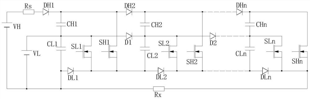
[0035] A cooperative pulse signal generating device provided by the present invention includes a high-voltage DC power supply VH, a low-voltage DC power supply VL, and at least one set of signal generating circuits;

[0036] The high-voltage direct current power supply VH is used to output high-voltage direct current to the high-voltage input terminal of the signal generating circuit;

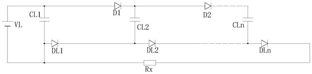
[0037] The low-voltage direct current power supply VL is used to output low-voltage direct current to the low-voltage input terminal of the signal generating circuit;

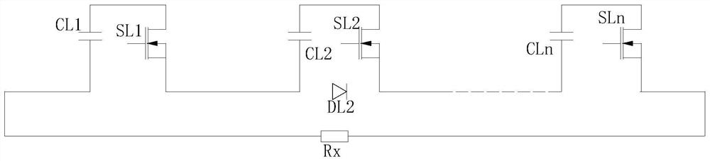
[0038] The pulse signal generating circuit has a high-voltage input terminal connected to the output terminal of the high-voltage DC power supply VH, and a low-voltage input terminal connected to the output terminal of the low-voltage DC power supply VL, for selectively outputting a high-voltage ...


PUM


Abstract

The invention provides a collaborative pulse signal generating device. The collaborative pulse signal generating device comprises a high-voltage direct-current power supply VH, a low-voltage direct-current power supply VL and at least one group of signal generating circuits. The high-voltage direct-current power supply VH is used for outputting high-voltage direct current to the high-voltage inputend of the signal generation circuit. The low-voltage direct-current power supply VL is used for outputting low-voltage direct current to the low-voltage input end of the signal generation circuit. The high-voltage input end of the pulse signal generation circuit is connected with the output end of the high-voltage direct-current power supply VH, and the low-voltage input end of the pulse signalgeneration circuit is connected with the output end of the low-voltage direct-current power supply VL and used for selectively outputting a high-voltage pulse signal or a low-voltage pulse signal to aload. Through the structure, high-voltage pulses can be generated in the same pulse signal generating device, and low voltage pulse can be generated, so as to perform selective switching according todifferent requirements and especially ablate completely with a large ablation volume when applied to tumor treatment, and the synergistic effect of high-pressure nanosecond pulses and microsecond pulses can be combined. The problem of tumor heterogeneity is solved, tumor stem cells are ablated, and the immune mechanism of an organism to tumors is stimulated.

Description

technical field [0001] The invention relates to a signal generating device, in particular to a coordinated pulse signal generating device. Background technique [0002] Pulse power technology is developing rapidly, and its application fields are constantly expanding, such as tumor treatment, food processing, water treatment, plasma generation, etc. During tumor treatment, pulse signals are used for tumor ablation. In the prior art, the main generation of pulse signals Ways include forming lines, Marx circuits, linear transformer driver (Linear Transformer Driver, LTD) circuits, etc. However, the existing pulse signal generating equipment can only generate a single pulse signal, such as only generating high-voltage pulse signals, or only Generate low-voltage pulse signals, resulting in a single function, incomplete tumor ablation, limited ablation volume, and inability to selectively kill tumor cells and tumor stem cells. In addition, the existing pulse generation circuit has...

Claims


Application Information

Patent Timeline
Patent Type & Authority Patents(China)
IPC IPC(8): H03K7/08A61B18/12
CPCA61B18/1206A61B2018/00577H03K7/08
Inventor 董守龙姚陈果余亮马剑豪王艺麟曾伟荣
Owner HANGZHOU WKNIFE MEDICAL TECH CO LTD
Why Eureka
Try Eureka