Transmission method, transmission device, and program
A sending method and illuminant technology, which are applied in the fields of sending, sending devices and programs, and can solve problems such as difficult cost and insufficient computing power
- Summary
- Abstract
- Description
- Claims
- Application Information
AI Technical Summary
Problems solved by technology
Method used
Image
Examples
Embodiment approach 1
[0433] Embodiment 1 will be described below.
[0434] (Observation of brightness of light emitting part)
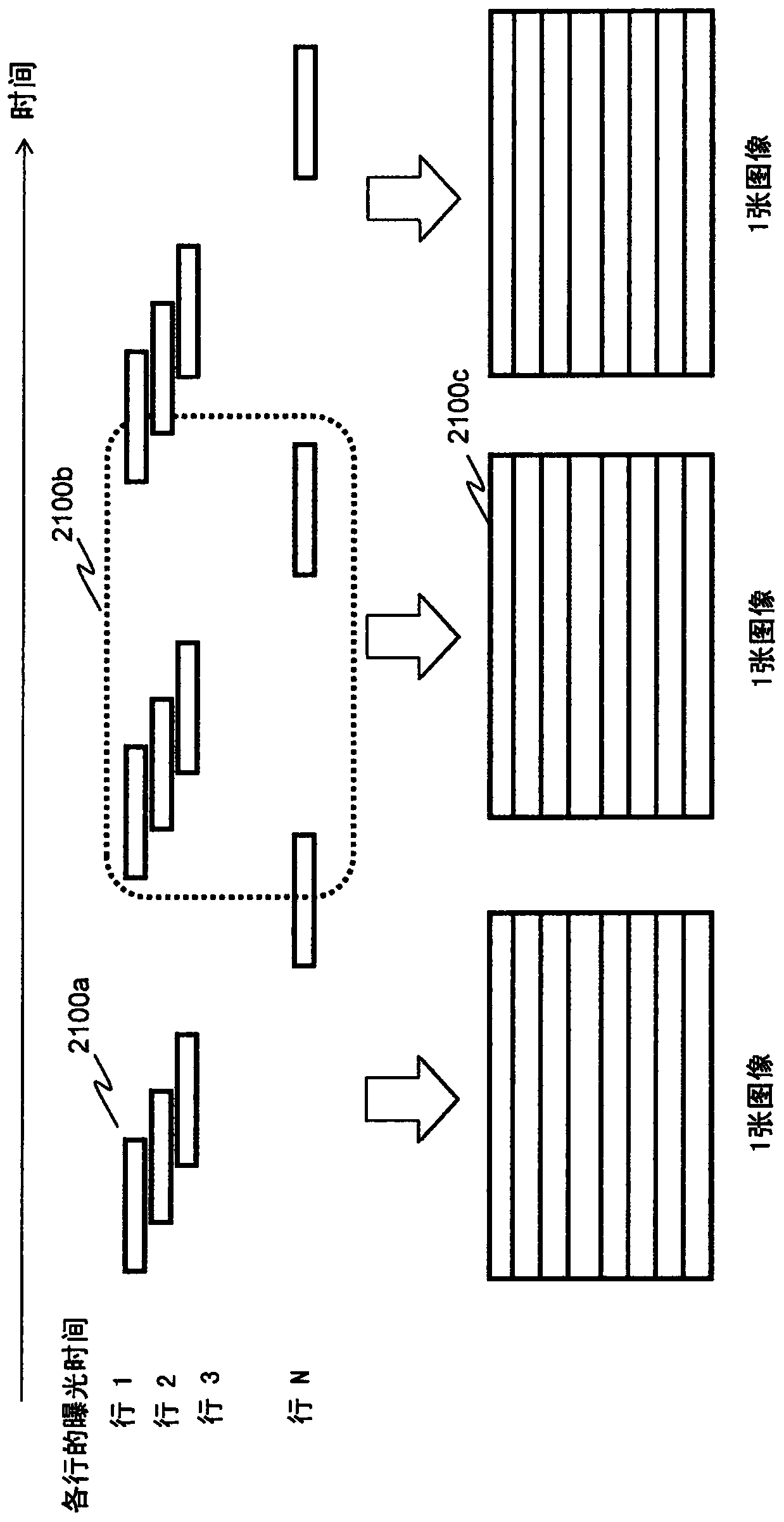
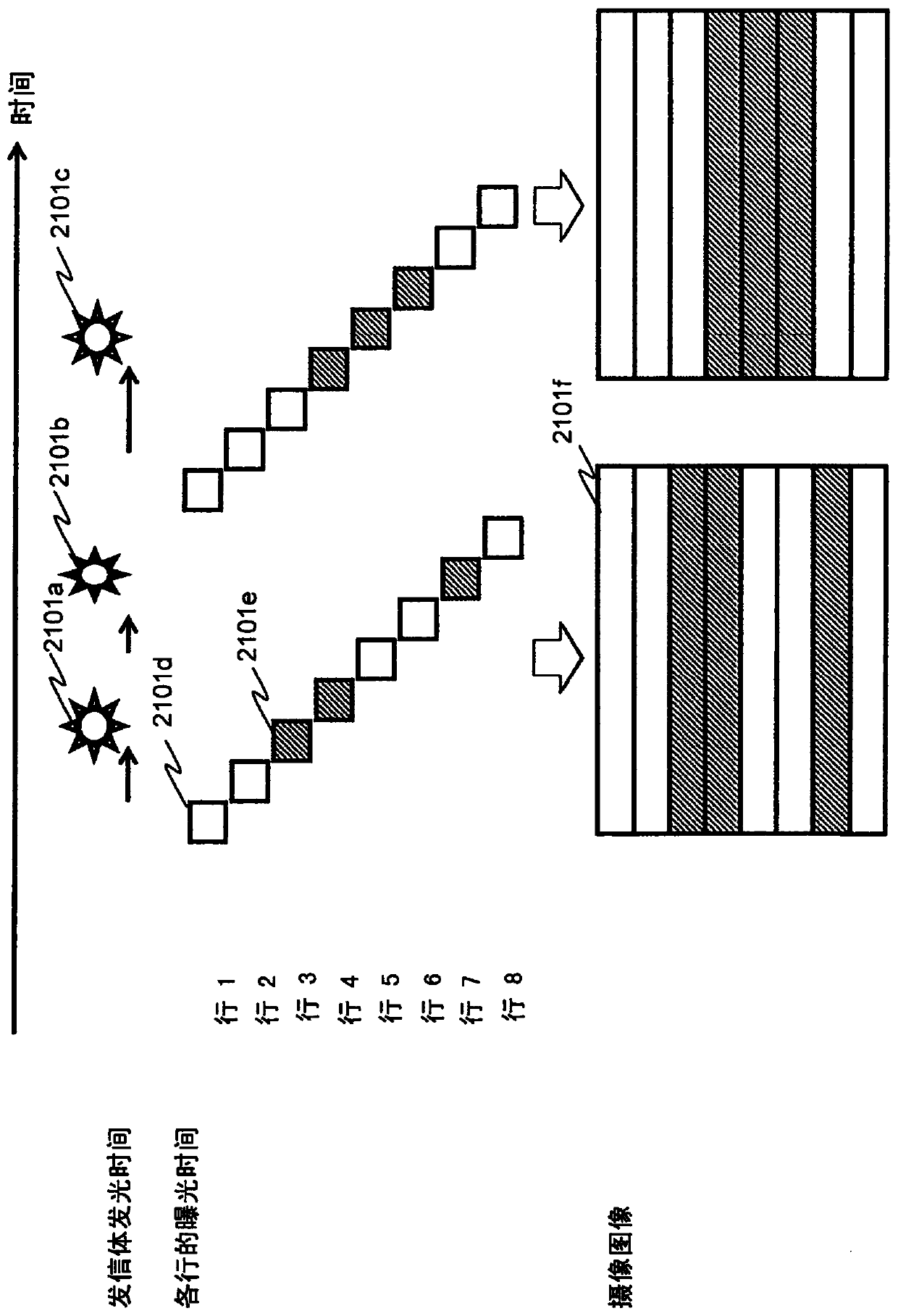
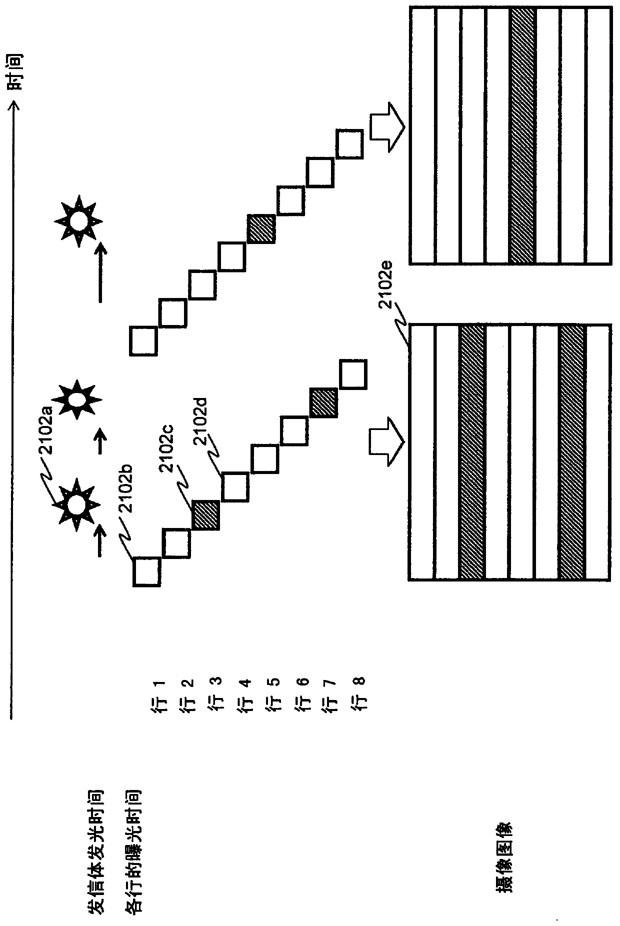
[0435] There is proposed an imaging method that does not expose all imaging elements at the same timing when capturing one image, but starts and ends exposure at different timings for each imaging element. figure 1 This is an example in which the imaging elements arranged in one row are simultaneously exposed, and the exposure start timings are shifted in the order of the row from the closest to the farthest, and images are taken. Here, it is called an exposure line of an imaging element exposed at the same time, and a row of pixels on an image corresponding to the imaging element is called a bright line.
[0436] In the case of imaging a flickering light source on the entire surface of the imaging element using this imaging method, if figure 2 In this way, bright lines (lines of brightness and darkness of pixel values) along the exposure line are generated on the captur...
Embodiment approach 2
[0469] In this embodiment, each application example using a receiver such as a smartphone as the information communication device K90 of the first embodiment and a transmitter that transmits information as a blinking pattern of a light source such as LED and / or organic EL will be described.
[0470] In the following description, the normal photography mode or photography in the normal photography mode is called normal photography, and the visible light communication mode or photography in the visible light communication mode is called visible light photography (visible light communication). In addition, intermediate mode imaging may be used instead of normal imaging and visible light imaging, and intermediate images may be used instead of composite images described later.
[0471] Figure 7 It is a diagram showing an example of the imaging operation of the receiver of the present embodiment.
[0472] The receiver 8000 switches between shooting modes such as normal shooting, v...
Embodiment approach 3
[0547] In this embodiment, each application example using a receiver such as a smartphone and a transmitter that transmits information as a blinking pattern of LED or organic EL in the above-mentioned Embodiment 1 or 2 will be described.
[0548] Figure 26 It is a diagram showing an example of the processing operations of the receiver, the transmitter, and the server according to the third embodiment.
[0549] For example, the receiver 8142 configured as a smartphone acquires position information indicating its own position, and transmits the position information to the server 8141 . In addition, the receiver 8142 acquires position information when receiving other signals, for example, using GPS or the like. The server 8141 transmits to the receiver 8142 a list of IDs associated with the positions indicated by the position information. In the ID list, for each ID such as "abcd", the ID and information associated with the ID are included.
[0550] The receiver 8142 receives...
PUM
 Abstract
Description
Claims
Application Information
 - R&D
- Intellectual Property
- Life Sciences
- Materials
- Tech Scout
- Unparalleled Data Quality
- Higher Quality Content
- 60% Fewer Hallucinations
Browse by: Latest US Patents, China's latest patents, Technical Efficacy Thesaurus, Application Domain, Technology Topic, Popular Technical Reports.
© 2025 PatSnap. All rights reserved.Legal|Privacy policy|Modern Slavery Act Transparency Statement|Sitemap|About US| Contact US: help@patsnap.com


