
Guide discharge device

A technology of discharging device and material, applied in metal processing, metal processing equipment, manufacturing tools, etc., can solve the problems of collision, inability to clamp, and small clamping area.

Pending Publication Date: 2019-08-02
SHENZHEN COLIBRI TECH
View PDF0 Cites 0 Cited by
  • Summary
  • Abstract
  • Description
  • Claims
  • Application Information

AI Technical Summary

Problems solved by technology

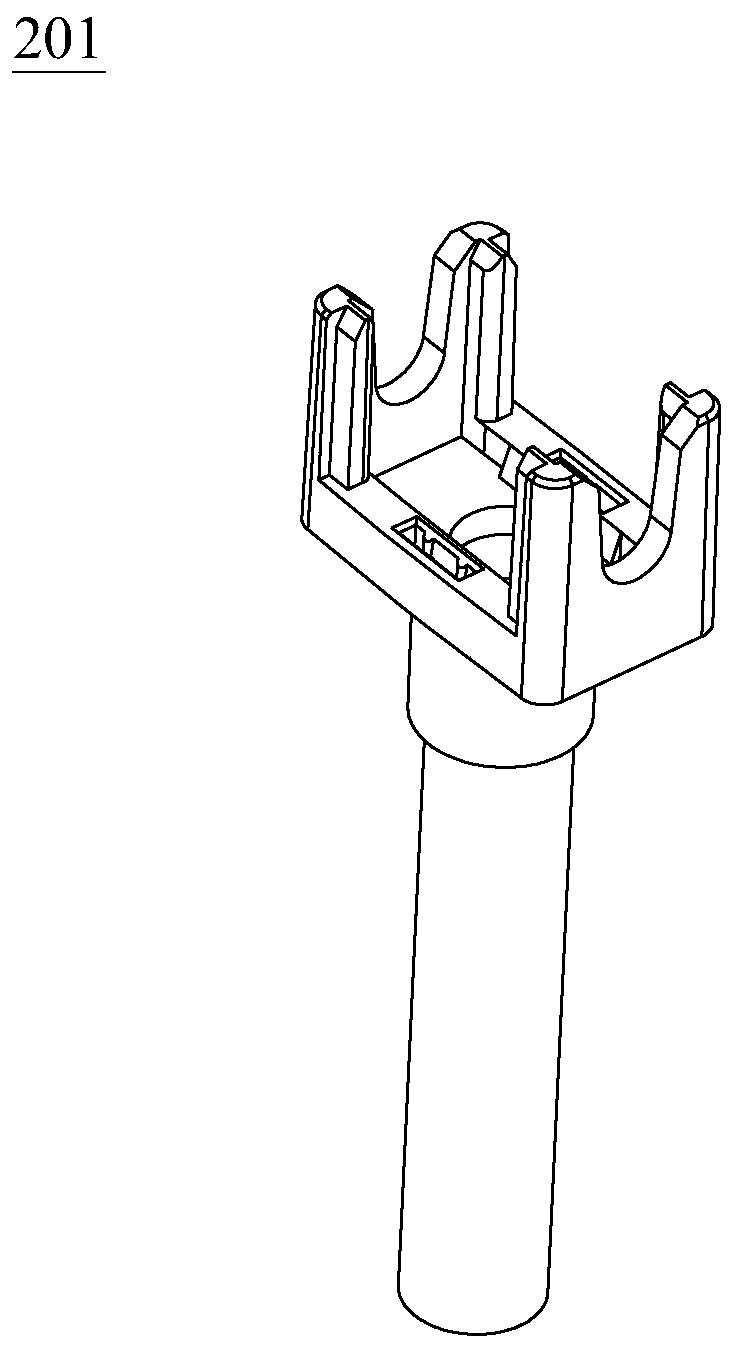
[0002] In the automatic assembly and production process of the electronic cigarette holder, such as figure 1 As shown, there is a slender steel pipe material 201 inside the electronic cigarette that needs to be assembled. Due to the special structure of the assembly, the tooling cannot clamp the middle part of the steel pipe material 201 during assembly, but can only clamp the head of the steel pipe material 201, thus causing The clamping area is relatively small, and the steel pipe material 201 is prone to skewing. The skewed steel pipe material 201 often collides with the edge of the top of the round hole of the positioning block of the carrier, and cannot enter the round hole of the positioning block, resulting in abnormal shutdown and tooling damage. , product scrapping phenomenon

Method used


Image

  • Guide discharge device
  • Guide discharge device
  • Guide discharge device

Examples


Embodiment Construction

[0028] The present invention will be further described below with reference to the accompanying drawings and preferred embodiments, but the embodiments of the present invention are not limited thereto.

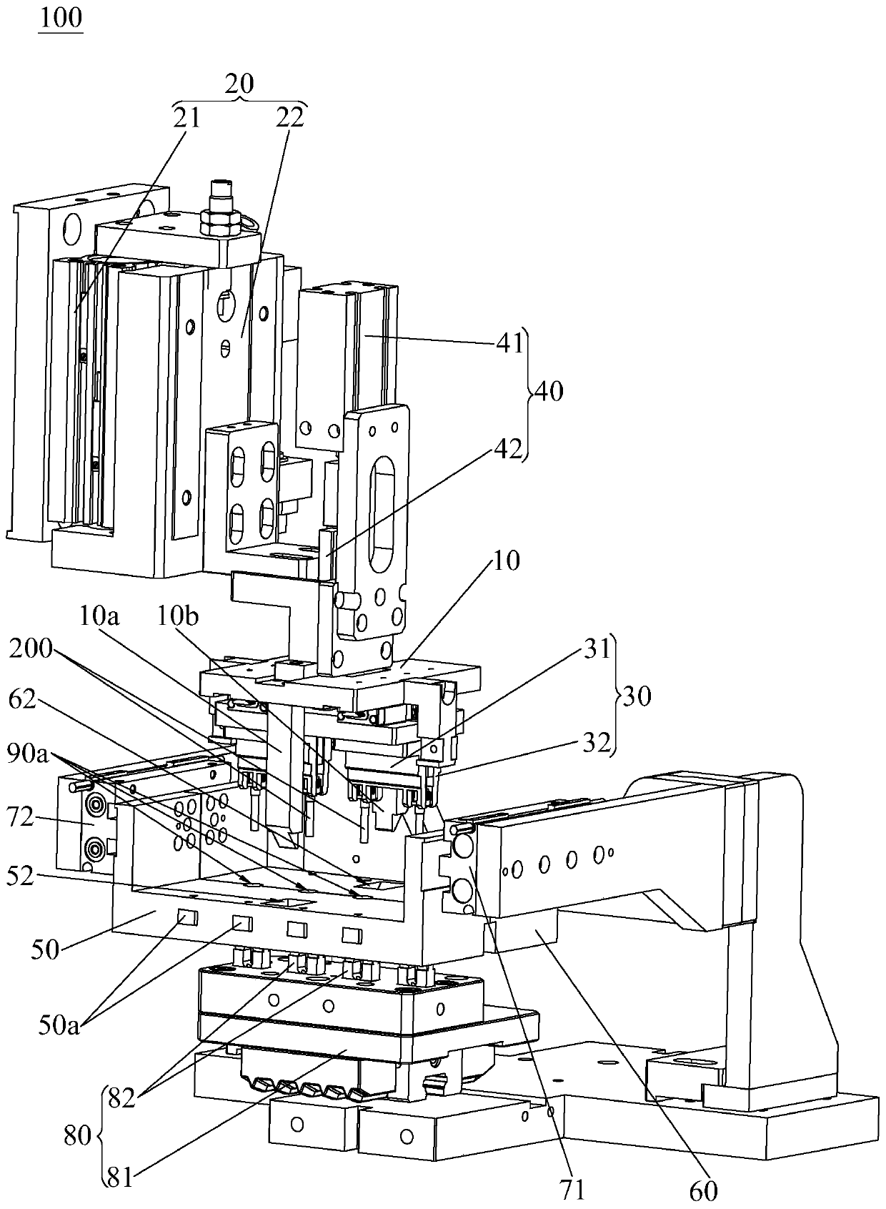
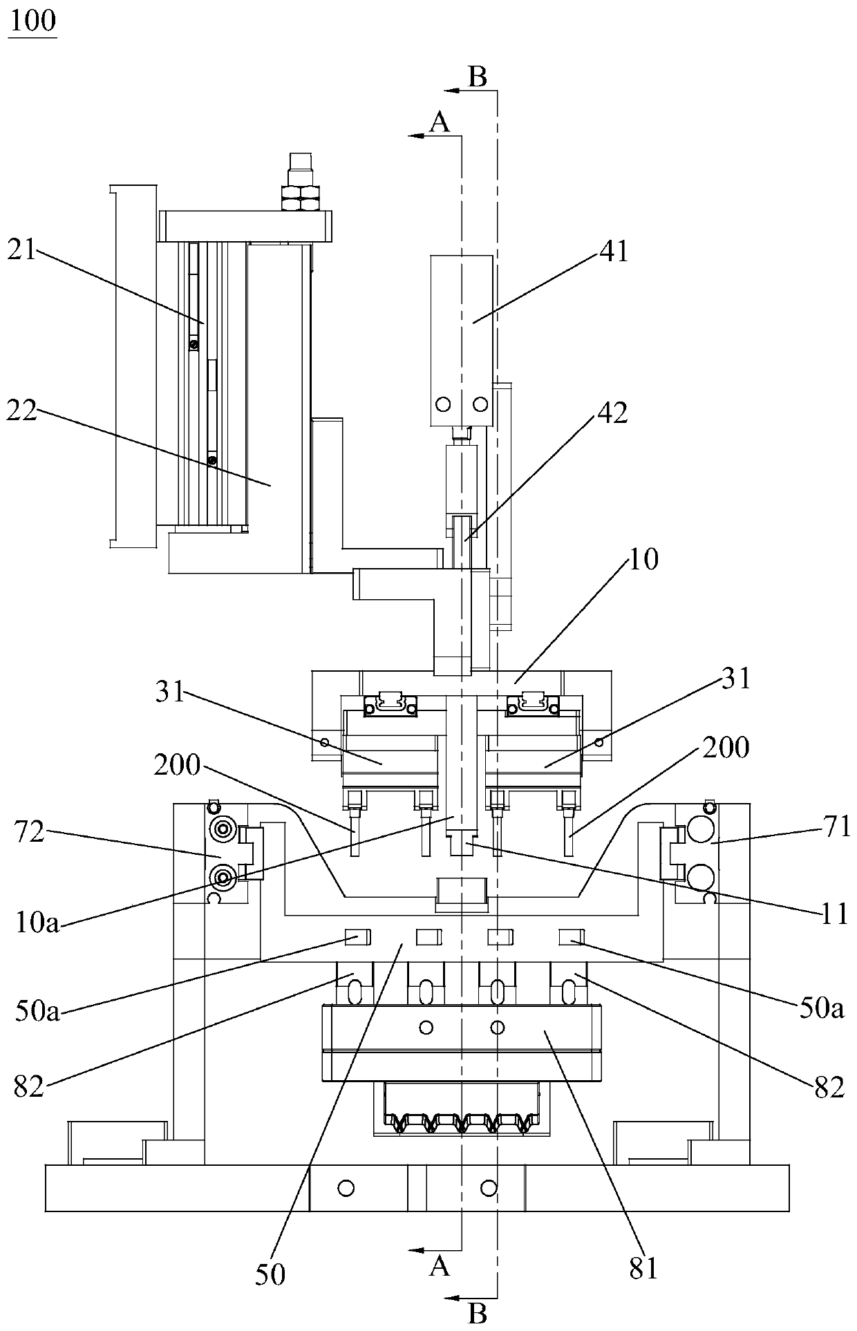
[0029] see Figure 2 to Figure 10 , the guiding and discharging device 100 of the present invention is suitable for guiding the material 200 when discharging, wherein the guiding and discharging device 100 of the present invention includes a lifting frame 10, a lifting drive mechanism 20, a clamping mechanism 30, a clamping The opening and closing drive mechanism 40, the first straightening splint 50, the second straightening splint 60, the first stretching guide post 10a, the second stretching guide post 10b and the straightening and closing drive mechanism (not marked in the figure), the lifting frame 10 is set On the lifting driving mechanism 20, the lifting driving mechanism 20 drives the lifting frame 10 to move vertically up and down. The clamping mechanism 30 and the c...


PUM


Abstract

The invention provides a guide discharge device. The guide discharge device comprises a lifting frame, a lifting driving mechanism, a clamping mechanism, a clamping opening and closing driving mechanism, a first guide clamping plate, a second guide clamping plate, a first spreading guide post, a second spreading guide post and a guide closing driving mechanism. The lifting driving mechanism drivesthe lifting frame to vertically move up and down. The clamping opening and closing driving mechanism drives the clamping mechanism to close to clamp a material or open to release the material. When the first guide clamping plate and the second guide clamping plate are closed, a first half-funnel-shaped groove and a corresponding second half-funnel-shaped groove are closed to form a first guide funnel allowing the guided material to vertically downwards penetrate through. After the lower end of the material penetrates through the first guide funnel, the first spreading guide post moving downwards pushes the first guide clamping plate to move leftwards, and the second spreading guide post moving downwards pushes the second guide clamping plate to move rightwards, so that the first guide clamping plate and the second guide clamping plate get away from each other to open to avoid the clamping mechanism to enable the clamping mechanism to continuously move downwards to convey the material.The first guide clamping plate and the second guide clamping plate are both in transmission connection with the guide closing driving mechanism.

Description

technical field [0001] The invention relates to the technical field of automatic assembly production equipment, in particular to a guiding and discharging device. Background technique [0002] In the automatic assembly and production process of the electronic cigarette holder, such as figure 1 As shown, there is a slender steel pipe material 201 inside the electronic cigarette that needs to be assembled. Due to the special structure of the assembly, the tooling cannot clamp the middle part of the steel pipe material 201 during assembly, but can only clamp the head of the steel pipe material 201, thus causing The clamping area is relatively small, and the steel pipe material 201 is prone to skewing. The skewed steel pipe material 201 often collides with the edge of the top of the round hole of the positioning block of the carrier, and cannot enter the round hole of the positioning block, resulting in abnormal shutdown and tooling damage. , Product scrap phenomenon. [0003]...

Claims


Application Information

Patent Timeline
Patent Type & Authority Applications(China)
IPC IPC(8): B23P19/00
CPCB23P19/002
Inventor 邹小波易晶詹友仁
Owner SHENZHEN COLIBRI TECH
Learn More