
A jig for assembly of motor components

A technology for assembling tooling and motor components, applied in the direction of electric components, electromechanical devices, electrical components, etc., can solve the problems of stator winding damage, prone to skewing, etc., and achieve the effect of high installation accuracy and strong stability

Active Publication Date: 2020-12-04
JIANGSU DAZHONG ELECTRIC MOTOR
View PDF4 Cites 0 Cited by
  • Summary
  • Abstract
  • Description
  • Claims
  • Application Information

AI Technical Summary

Problems solved by technology

[0004] 1. When manually holding the rotating shaft, because the left end of the rotating shaft is heavy, the rotating shaft is prone to skew when installed in the motor casing, and the rotor core on the rotating shaft will touch the stator winding in the motor casing, causing damage to the stator winding;

Method used


Image

  • A jig for assembly of motor components
  • A jig for assembly of motor components
  • A jig for assembly of motor components

Examples


Embodiment Construction

[0035] In order to make the technical means, creative features, goals and effects achieved by the present invention easy to understand, the present invention will be further described below in conjunction with specific illustrations. It should be noted that, in the case of no conflict, the embodiments in the present application and the features in the embodiments can be combined with each other.

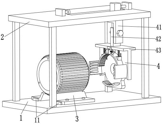
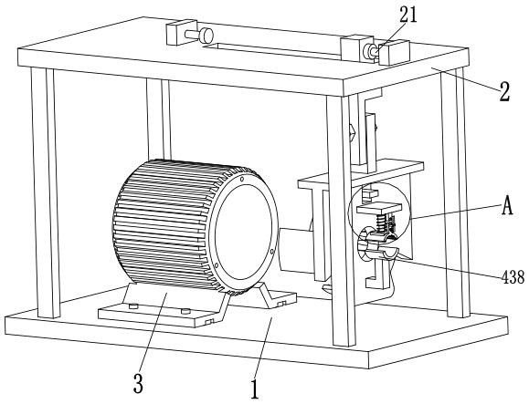
[0036] like Figure 1 to Figure 9 As shown, a jig for assembly of motor components includes a bottom plate 1, an upper support plate 2, a motor casing 3 and a lifting device 4, the upper support plate 2 is located directly above the bottom plate 1, and the upper support plate 2 is installed on the bottom plate On the top of the outer end of 1, the middle part of the upper support plate 2 is provided with a conveying trough with a chute on the side wall, the lifting device 4 is connected with the upper support plate 2, and the motor casing 3 is placed on the top of the left end of the...


PUM


Abstract

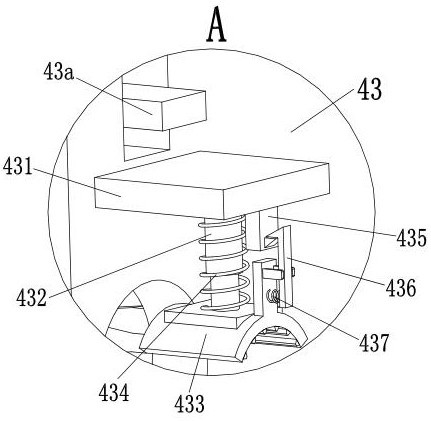
The invention relates to a motor component assembling fixture, which comprises a bottom plate, an upper support plate, a motor housing and a lifting device. The upper support plate is located right above the bottom plate, and the upper support plate is installed on the top of the outer end of the bottom plate. A conveying slot with a chute in the side wall thereof is arranged in the middle of theupper support plate. The lifting device is connected with the upper support plate. The motor housing is placed on the top of the left end of the bottom plate. The rotating shaft of a motor can be locked and inserted into the middle of the motor housing by the lifting device. The lifting device includes a lifting slide frame, a lifting adjustment block, a clamping bracket, a supporting plate, a clamping and pressing frame and clamping and pressing springs. In the prior art, because the left end of the rotating shaft is heavy, the rotating shaft is prone to skew when held by people and installedinto the motor housing, and the rotor core on the rotating shaft will touch the stator winding in the motor housing to cause damage to the stator winding. The problem in the prior art is solved by using the motor component assembling fixture of the invention.

Description

technical field [0001] The invention relates to the technical field of motor production, in particular to a jig for assembling a motor assembly. Background technique [0002] Among existing motors, three-phase asynchronous motors have been widely used because of their simple structure, reliable operation, light weight and low price. Three-phase asynchronous motors need to be frequently assembled in the production assembly workshop or maintenance workshop of the factory. The three-phase asynchronous motor mainly includes the motor casing, rotating shaft, rotor core, left and right end covers, etc., in which the stator is fixed inside the motor casing, and the rotor core Locks in the middle of the shaft. [0003] like Figure 7 As shown in the figure, when assembling a three-phase asynchronous motor, it is necessary to lock the right end cover on the rotating shaft first, then insert the rotating shaft into the motor casing, then lock the right end cover of the motor on the c...

Claims


Application Information

Patent Timeline
Patent Type & Authority Patents(China)
IPC IPC(8): H02K15/14
CPCH02K15/14
Inventor 付心怡陆友峰
Owner JIANGSU DAZHONG ELECTRIC MOTOR
Learn More