Portable device for cutting beam steel
A cutting device and portable technology, which can be used in sawing machine devices, metal sawing equipment, metal processing equipment, etc., can solve problems such as inclination of cutting angle, and achieve the effect of improving production efficiency and preventing safety accidents.
- Summary
- Abstract
- Description
- Claims
- Application Information
AI Technical Summary
Problems solved by technology
Method used
Image

Examples
Embodiment Construction
[0038] Embodiments of the present invention will be described in detail below in conjunction with the accompanying drawings.
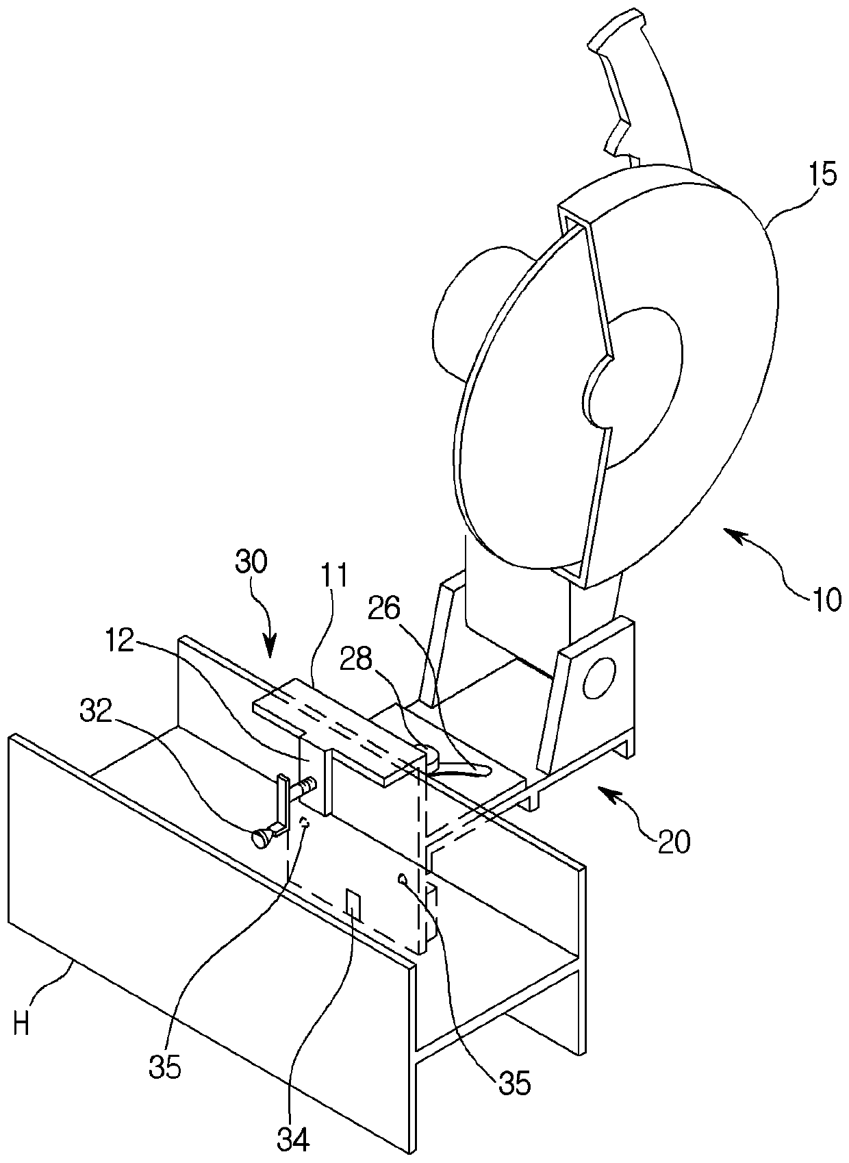
[0039] The invention discloses a device for cutting various shaped steels with a portable structure. The present invention targets cutting of H-shaped steel, L-shaped steel, C-shaped steel, etc., but is not necessarily limited thereto. That is, in addition to H-shaped steel, L-shaped steel, and C-shaped steel, it can also be applied to cases with more specific cross-sectional shapes. Portable structures target a size and weight that a single operator can lift or push to move them.
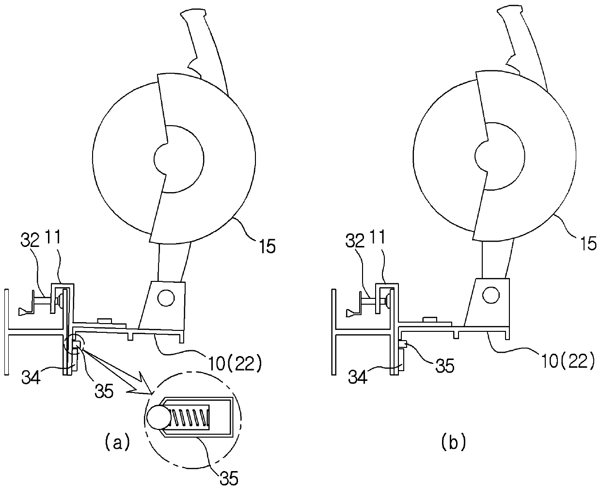
[0040] According to the invention, the body 10 carries a cutting machine 15 on a bent structural frame 11 resting on section steel. Body 10 has word or The font bending structure is used to directly rest on the section steel as the cutting object instead of on the ground. It can be clamped after the frame 11 is mounted on the part of the H-shaped steel, L-shaped stee...
PUM
 Abstract
Description
Claims
Application Information
 - Generate Ideas
- Intellectual Property
- Life Sciences
- Materials
- Tech Scout
- Unparalleled Data Quality
- Higher Quality Content
- 60% Fewer Hallucinations
Browse by: Latest US Patents, China's latest patents, Technical Efficacy Thesaurus, Application Domain, Technology Topic, Popular Technical Reports.
© 2025 PatSnap. All rights reserved.Legal|Privacy policy|Modern Slavery Act Transparency Statement|Sitemap|About US| Contact US: help@patsnap.com