Steel bottle heating safety device

A safety device and technology of steel cylinders, which are applied in the method of container discharge, container filling method, gas/liquid distribution and storage, etc., can solve the problems of increased pressure of steel cylinders, safety accidents, explosions, etc., so as to ensure safe use and prevent safety effect of accident

Inactive Publication Date: 2016-07-27
锦州市润达燃气节能技术研究所
View PDF0 Cites 0 Cited by
  • Summary
  • Abstract
  • Description
  • Claims
  • Application Information

AI Technical Summary

Problems solved by technology

But in actual use, after the angle valve of the steel cylinder is closed, once the maximum safety of the heating device fails, resul

Method used


Image

  • Steel bottle heating safety device
  • Steel bottle heating safety device

Examples


Example Embodiment

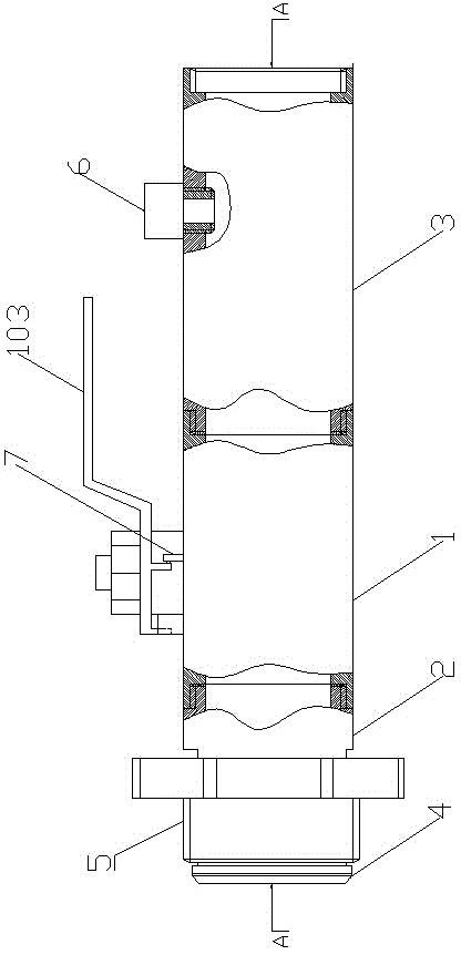
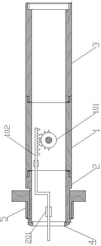
[0010] As shown in the figure, the steel cylinder heating safety device of the present invention includes a ball valve 1. The two ports of the ball valve 1 are respectively connected to the pipe head one 2 and the pipe head two 3, and the outer port of the pipe head two is equipped with a sealing rubber gasket 4. A connecting wheel 5 for connecting the steel cylinder is sleeved on the tube head 2, and the outer port of the tube head 2 3 is provided with internal threads; the valve core 101 side of the ball valve 1 is gear-shaped, and is connected to the gear part of the valve core 101 There is a rack 102, the other end of the rack 102 is led out from the outer port of the tube head-2, and a limiting groove 201 is provided on the inner wall of the tube head-2 corresponding to the rack 102, and the rack 102 is located in the limiting groove 201; a pressure switch 6 is provided on the second pipe 3, and the detection end of the pressure switch 6 is located in the second pipe 3; the...


PUM


Abstract

The invention provides a steel bottle heating safety device, which ensures the safe operation of a steel bottle heating device, and eliminates safety incident due to limitless heating of the heating device. The steel bottle heating safety device includes a ball valve; two ports of the ball valve are respectively connected to a tube head 1 and a tube head 2; an outer port of the tube head 1 is equipped with a sealed cushion; a cock wheel for connecting the steel bottle sleeves on the tube head 1; an outer port of tube head 2 is equipped with an internal thread; one side of the valve element of the ball valve has a gear shape; the gear portion of the valve element is connected with a tooth bar, and the other end of the valve element is introduced by the outer port of the tube head 1; a spacing groove is arranged on the position corresponding to the tooth bar on the inner wall of the tube head 1; the tooth bar is located in the limiting groove; a pressure switch is arranged on the tube head 2; a detection end of the pressure switch is located in the tube head 2; a microswitch is arranged on the ball valve body on the position corresponding to an operating handle of the valve body; and the microswitch is in series connection with the pressure switch.

Description

technical field [0001] The invention relates to a steel cylinder heating safety device. Background technique [0002] In the cold season, due to the low ambient temperature, the self-gasification of the liquid in the steel cylinder cannot be used by the stove; in other seasons, if the stove is used continuously, the self-gasification of the liquid in the steel cylinder cannot be used by the stove, and even the outside of the steel cylinder is frosted. A large amount of residual liquid is produced in the tank, resulting in great waste. For this reason, a heating device is arranged on the outer skin of the steel cylinder, and the steel cylinder is heated by the heating device to improve the gasification effect, so as to meet the gasification capacity requirement of the continuous use of the cooker. But in actual use, after the angle valve of the steel cylinder is closed, once the highest safety of the heating device fails, resulting in unlimited heating, the pressure inside t...

Claims


Application Information

Patent Timeline
IPC IPC(8): F17C13/00F17C13/04
Inventor 肖北雁武海涛张众王希李文科
Owner 锦州市润达燃气节能技术研究所
Why Eureka
Try Eureka