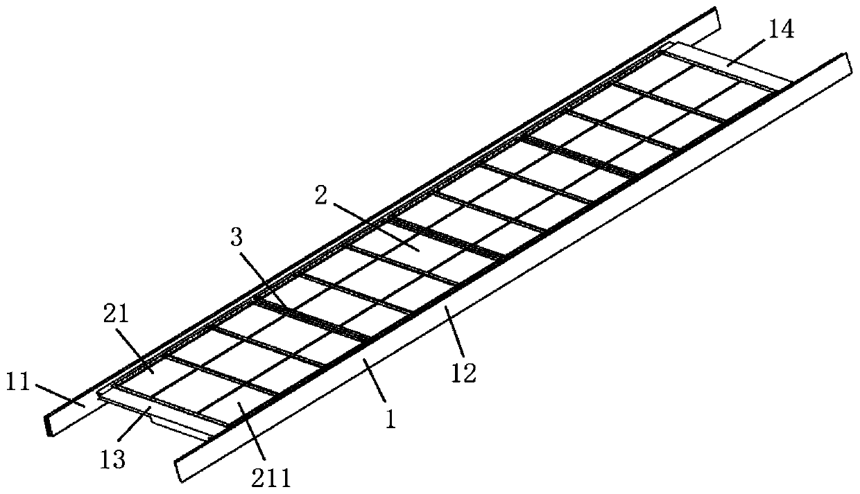
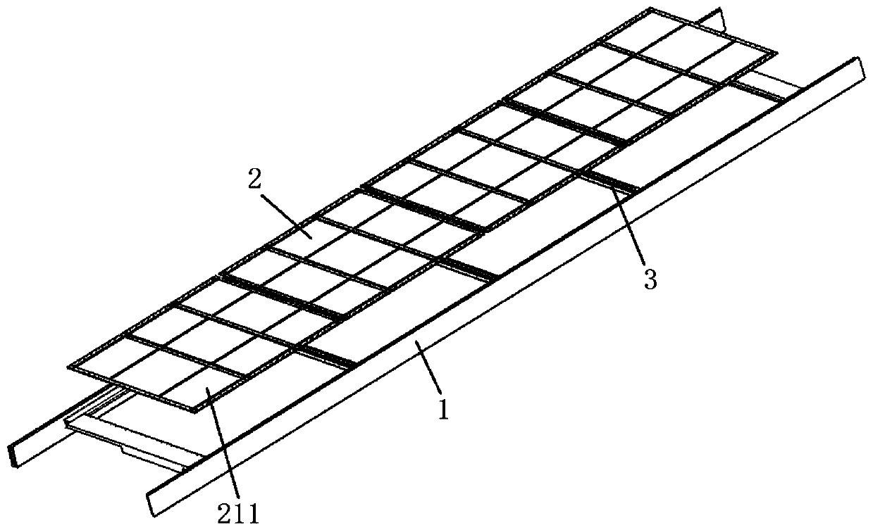
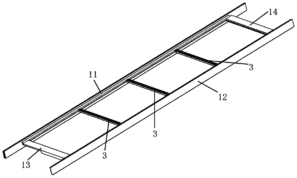
Vehicle body floor structure and railway vehicle with vehicle body floor structure

A floor and car body technology, applied in the field of rail vehicles, can solve the problems of easy deformation of the floor of the car body and increase of the weight of the car body, etc.

Inactive Publication Date: 2019-08-13
CRRC QINGDAO SIFANG CO LTD
View PDF9 Cites 7 Cited by
  • Summary
  • Abstract
  • Description
  • Claims
  • Application Information

AI Technical Summary

Problems solved by technology

[0005] The purpose of the present invention is to provide a car body floor structure and a rail vehicle with the same structure, to solve the problem that the car body floor in the prior art is usually integral, and it is necessary t

Method used


Image

  • Vehicle body floor structure and railway vehicle with vehicle body floor structure
  • Vehicle body floor structure and railway vehicle with vehicle body floor structure
  • Vehicle body floor structure and railway vehicle with vehicle body floor structure

Examples


Embodiment Construction

[0030] The specific implementation manners of the present invention will be further described in detail below in conjunction with the accompanying drawings and embodiments. The following examples are used to illustrate the present invention, but are not intended to limit the scope of the present invention.

[0031] In the description of the present invention, it should be noted that unless otherwise specified and limited, the terms "installation", "connection" and "connection" should be understood in a broad sense, for example, it can be a fixed connection or a detachable connection. Connected, or integrally connected; it may be mechanically connected or electrically connected; it may be directly connected or indirectly connected through an intermediary, and it may be the internal communication of two components. Those of ordinary skill in the art can understand the specific meanings of the above terms in the present invention in specific situations.

[0032] Such as Figure...


PUM


Abstract

The invention relates to the technical field of railway vehicles, and discloses a vehicle body floor structure and a railway vehicle with the vehicle body floor structure. The vehicle floor structurecomprises a floor frame, a floor body, and a plurality of support beams, wherein the floor body is detachably mounted on the floor frame, the floor body comprises a plurality of floor units, and adjacent floor units are detachably connected; each of the support beams is arranged on the floor frame and used for supporting the floor body, wherein one of the support beams is arranged between every two of the floor units. The vehicle body floor structure has the advantages of being modularized, detachable, light in weight, and low in welding quantity.

Description

technical field [0001] The invention relates to the technical field of rail vehicles, in particular to a vehicle body floor structure and a rail vehicle with the structure. Background technique [0002] At present, the floor of the rail vehicle body structure is mainly composed of aluminum alloy profiles and stainless steel plates. The interface connection mode between aluminum alloy profiles and stainless steel plates and the car body structure is mainly welding. However, welding will directly lead to the deformation of the aluminum alloy profile and stainless steel plate, that is, the overall shrinkage of the aluminum alloy profile and stainless steel plate. In view of this situation, a special process method is required to adjust the composition of the floor. Adjustment, however, is completely inconsistent with the trend of energy conservation and emission reduction. [0003] In addition, the existing floor of the car body is generally integral, that is, in order to mee...

Claims


Application Information

Patent Timeline
IPC IPC(8): B61D17/10
CPCB61D17/10
Inventor 张泽云郑伟蔡军爽郭志成田洪雷
Owner CRRC QINGDAO SIFANG CO LTD
Why Eureka
Try Eureka