Supercharge Your Innovation With Domain-Expert AI Agents!

Transformer structure

A technology of transformers and inductors, applied in transformer/inductor coils/windings/connections, preventing/reducing unwanted electrical/magnetic influences, etc., can solve problems such as unsatisfactory coupling coefficient quality factors

Active Publication Date: 2021-02-05
REALTEK SEMICON CORP
View PDF2 Cites 0 Cited by
  • Summary
  • Abstract
  • Description
  • Claims
  • Application Information

AI Technical Summary

Problems solved by technology

However, under the premise of satisfying the requirement of high inductance ratio in the transformer structure in the conventional technology, the coupling coefficient and quality factor between the two sets of inductors are often not ideal.

Method used


Image

  • Transformer structure
  • Transformer structure
  • Transformer structure

Examples


Embodiment Construction

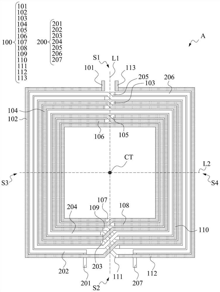
[0028] figure 1 It is a schematic diagram of a transformer structure according to an embodiment of the present application, which shows a top view of a transformer structure. In this embodiment, the transformer structure is arranged on the plane of the first area A, where a first imaginary straight line L1 and a second imaginary straight line L2 perpendicular to each other are drawn on the plane of the first area A, and the two imaginary straight lines intersect At the center point CT of the plane. Such as figure 1 As shown in , the first imaginary straight line L1 divides the plane from top to bottom, one end of which is the first side S1 of the plane, and the opposite end is the second side S2 of the plane. The second imaginary straight line L2 divides the plane from left to right, one end of which is the third side S3 of the plane, and the opposite end is the fourth side S4 of the plane.

[0029] Such as figure 1 As shown in , in this embodiment, the plane of the first ...


PUM


Abstract

The invention relates to a transformer structure which comprises a first inductor and a second inductor. The first inductor comprises a plurality of coils. The second inductor also comprises a plurality of coils, the second inductor and the first inductor are arranged in an interactive mode, and the second inductor and the first inductor are arranged on the same layer except for jumper wires. At least one coils of the first inductor is adjacent to the other coils of the first inductor and one coil of the second inductor.

Description

technical field [0001] This case involves an inductor structure, especially a transformer structure. Background technique [0002] The inductor structure is an indispensable component in today's integrated circuits, and the transformer structure is a component composed of inductors. However, under the premise of satisfying the requirement of high inductance ratio in the conventional transformer structure, the coupling coefficient and quality factor between the two sets of inductors are usually not ideal. Therefore, this kind of transformer structure urgently needs to be improved by people in the field. Contents of the invention [0003] One purpose of this case is to provide a transformer structure that has high mutual inductance (L value), better coupling coefficient (K value) and good quality factor (Q value). [0004] The implementation aspect of this case is a transformer structure, including a first inductor and a second inductor. The first inductor includes a plur...

Claims


Application Information

Patent Timeline
Patent Type & Authority Patents(China)
IPC IPC(8): H01F27/28H01F27/34
CPCH01F27/28H01F27/34
Inventor 颜孝璁简育生叶达勋
Owner REALTEK SEMICON CORP
Features
  • R&D
  • Intellectual Property
  • Life Sciences
  • Materials
  • Tech Scout
  • Unparalleled Data Quality
  • Higher Quality Content
  • 60% Fewer Hallucinations
Learn More