
Sludge drying equipment

A sludge drying and equipment technology, which is applied in the direction of dehydration/drying/concentrated sludge treatment, etc., can solve the problems of poor drying effect and low drying efficiency, and achieve the effect of simple structure, preventing drying effect, and simple use

Inactive Publication Date: 2019-08-16
HANGZHOU XIAOCHENG IND DESIGN CO LTD
View PDF6 Cites 0 Cited by
  • Summary
  • Abstract
  • Description
  • Claims
  • Application Information

AI Technical Summary

Problems solved by technology

[0002] Sludge needs to be dehydrated and dried before being incinerated. After dehydration, the sludge will become a mud cake, and the mud cake will still contain 40 to 50% of water. At this time, it needs to continue to dry, but the traditional The sludge drying equipment has low drying efficiency and poor drying effect

Method used


Image

  • Sludge drying equipment
  • Sludge drying equipment
  • Sludge drying equipment

Examples


Embodiment Construction

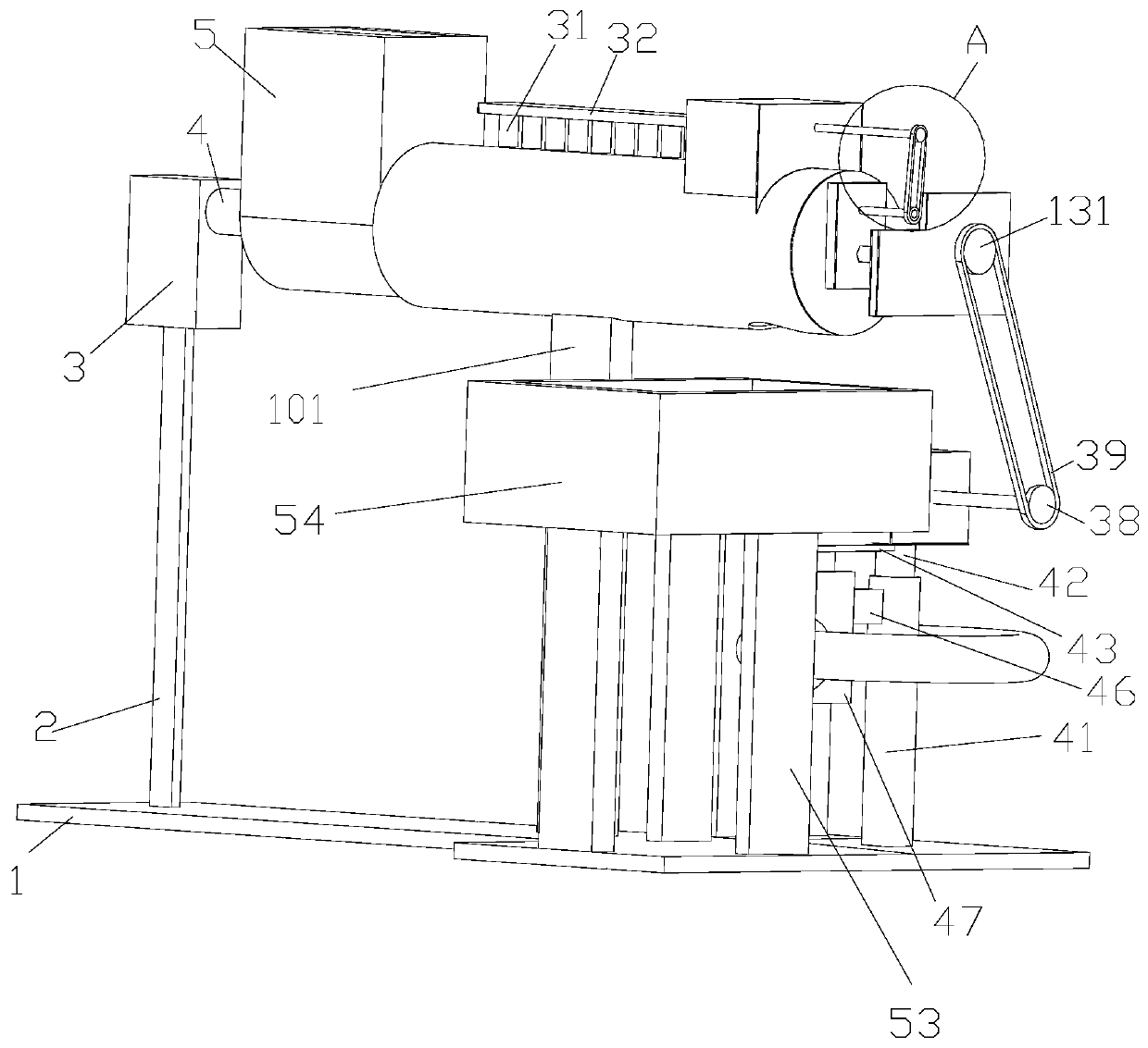
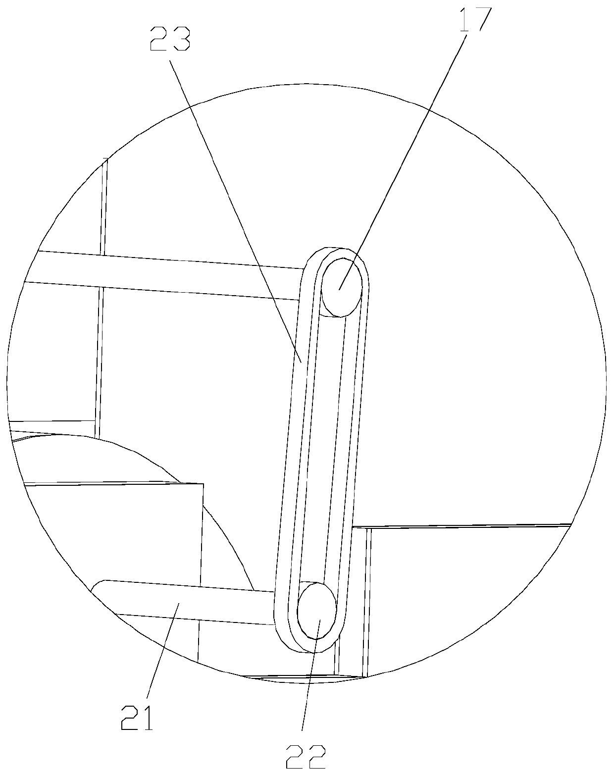
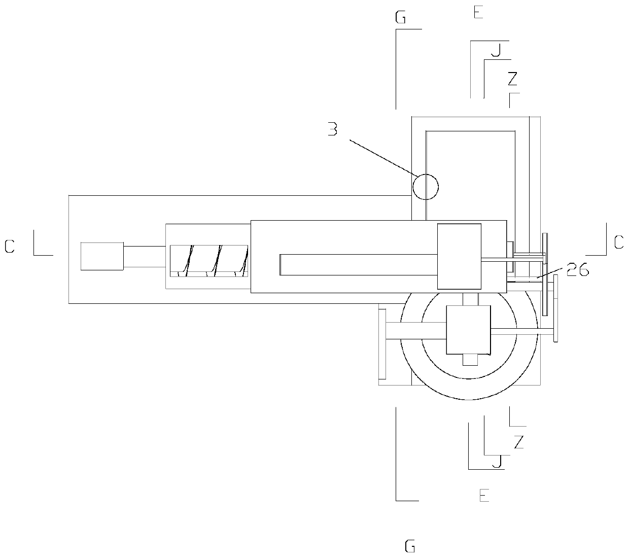
[0031] Such as Figure 1-14 As shown, a sludge drying equipment includes a machine base 1, a first vertical plate 2 fixedly arranged on the upper surface of the machine base 1, a transmission device arranged on the upper surface of the first vertical plate 2, and a fan installed on the transmission device The device, the turning device fixedly arranged on the right side of the upper surface of the machine base 1, is characterized in that: the transmission device includes a steam engine 3 fixedly arranged on the upper surface of the first vertical plate 2, and a steam pipe connected to the right end surface of the steam engine 3 4. It is connected to the crushing shell 5 arranged on the right end of the steam pipe 4, the crushing space 6 which is set in the crushing shell 5 and opens upward, and connected to the spiral shell 7 arranged on the right end wall of the crushing space 6. In the screw space 8 in the screw housing 7, the screw feeding shaft 9 that is arranged on the le...


PUM


Abstract

The invention discloses sludge drying equipment, the sludge drying equipment is characterized by comprising a machine base, a first vertical plate fixedly arranged on the upper surface of the machinebase, a transmission device arranged on the upper surface of the first vertical plate, a fan device arranged on the transmission device, and a flap device fixedly arranged on the right side of the upper surface of the machine base. The transmission device comprises a steam engine fixedly arranged on the upper surface of the first vertical plate, a steam pipeline communicated with the right end surface of the steam engine, a crushing shell communicated with the right end surface of the steam pipeline, a crushing space arranged in the crushing shell and opening upwards, a spiral shell communicated with the right end wall of the crushing space, a spiral space arranged in the spiral shell, a spiral feeding shaft rotationally arranged on the left end wall of the crushing space, and crushed sludge is dried while being conveyed through the transmission device.

Description

technical field [0001] The invention belongs to the field of sludge drying, and in particular relates to sludge drying equipment. Background technique [0002] Sludge needs to be dehydrated and dried before being incinerated. After dehydration, the sludge will become a mud cake, and the mud cake will still contain 40 to 50% of water. At this time, it needs to continue to dry, but the traditional Advanced sludge drying equipment has low drying efficiency and poor drying effect. Contents of the invention [0003] In order to overcome the deficiencies of the prior art, the present invention provides sludge drying equipment capable of drying sludge faster and better. [0004] In order to achieve the above object, the present invention adopts the following technical solutions: a sludge drying equipment, including a machine base, a first vertical plate fixed on the upper surface of the machine base, a transmission device set on the upper surface of the first vertical plate, and...

Claims


Application Information

Patent Timeline
Patent Type & Authority Applications(China)
IPC IPC(8): C02F11/13
CPCC02F11/12
Inventor 李颖
Owner HANGZHOU XIAOCHENG IND DESIGN CO LTD
Learn More