
Feeding precision control device for continuous mesh belt heat treatment furnace

A heat treatment furnace, precision control technology, applied in heat treatment furnaces, heat treatment equipment, furnaces, etc., can solve the problems of labor, large errors, product quality fluctuations, etc., to achieve the effect of liberating labor, reducing hardness dispersion, and improving product quality

Pending Publication Date: 2019-08-16
ZHOUSHAN 7412 FACTORY
View PDF0 Cites 0 Cited by
  • Summary
  • Abstract
  • Description
  • Claims
  • Application Information

AI Technical Summary

Problems solved by technology

[0002] Continuous mesh belt furnace is the most commonly used heat treatment equipment for automobile fasteners and other accessories. The final hardness dispersion is small, which requires that the feeding of the mesh belt furnace must be uniform. The traditional feeding method is mainly through manual work, with huge errors, resulting in fluctuations in product quality, and it is difficult to meet the requirements of customers and industries.

Method used


Image

  • Feeding precision control device for continuous mesh belt heat treatment furnace
  • Feeding precision control device for continuous mesh belt heat treatment furnace
  • Feeding precision control device for continuous mesh belt heat treatment furnace

Examples


Embodiment Construction

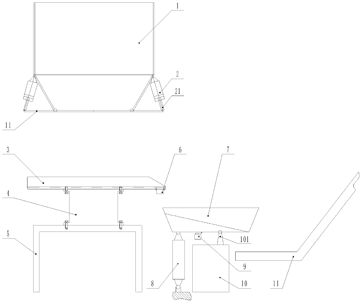
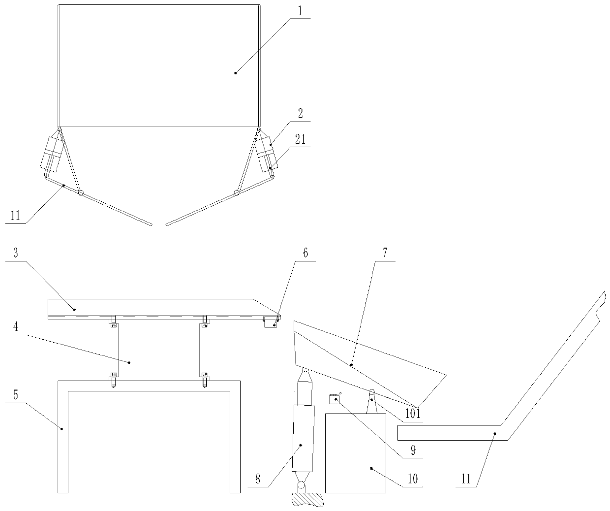
[0019] Such as figure 1 , image 3 As shown, the continuous mesh belt heat treatment furnace feeding precision control device described in the embodiment of the present invention includes a workbench 5, a flat feeder 4 is installed at the middle position of the workbench 5, and a feeding platform 3 is installed on the top of the flat feeder 4 , the feeding platform 3 is processed with a toothed surface 31, and the electromagnet 6 is installed on the right side of the bottom of the feeding platform 3; the upper part of the feeding platform 3 is the storage hopper 1, and the lower part of the storage hopper 1 is symmetrically installed with the cylinder I2, and the top of the cylinder I2 is connected to the side of the storage hopper 1 Hinged, the bottom of the storage hopper 1 is symmetrically installed with the bottom plate 11, the middle part of the bottom plate 11 is hinged with the bottom edge of the storage hopper 1, the bottom of the cylinder rod 21 of the cylinder I2 is ...


PUM


Abstract

The invention discloses a feeding precision control device for a continuous mesh belt heat treatment furnace. The feeding precision control device for the continuous mesh belt heat treatment furnace comprises a workbench, a horizontal conveyor is arranged in the middle of the workbench, a feeding table is arranged at the top of the horizontal conveyor, an electromagnet is arranged on the right side of the bottom of the feeding table, a storage hopper is arranged above the feeding table, air cylinders I are symmetrically arranged on the left side and the right side of the lower portion of the storage hopper, bottom plates are symmetrically arranged on the left side and the right side of the bottom of the storage hopper, the bottom of air cylinder rods of the air cylinders I is hinged to oneside of the bottom plates, the middle of the bottom of a turnover hopper on the right side of the feeding table is connected with an electronic scale, the left side of the bottom of the turnover hopper is connected with an air cylinder II, and a microswitch is arranged below the turnover hopper. During operation, the part falls from the storage hopper to the feeding table, under the action of thevibration of the horizontal conveyor, the part moves along the feeding table to enter the turnover hopper, when the weight displayed by the electronic scale reaches a set value, the electromagnet iselectrified to prevent the part from falling, the air cylinder II pushes the turnover hopper so as to pour the part into the conveying mesh belt. According to the device, the loading weight of the product can be accurately controlled, the product quality is improved, and the structure is reasonable and effective.

Description

technical field [0001] The invention relates to a precision control device for feeding materials in a continuous mesh belt heat treatment furnace. Background technique [0002] Continuous mesh belt furnace is the most commonly used heat treatment equipment for automobile fasteners and other accessories. The final hardness dispersion is small, which requires that the feeding of the mesh belt furnace must be uniform. The traditional feeding method is mainly through manual work, with huge errors, resulting in fluctuations in product quality, and it is difficult to meet the requirements of customers and the industry. Contents of the invention [0003] Aiming at the deficiencies in the above problems, the present invention provides a precision control device for loading materials in a continuous mesh belt heat treatment furnace. [0004] In order to achieve the above object, the present invention provides a precision control device for feeding continuous mesh belt heat treatme...

Claims


Application Information

Patent Timeline
Patent Type & Authority Applications(China)
IPC IPC(8): C21D1/00C21D9/00
CPCC21D1/00C21D9/0018C21D9/0068
Inventor 唐建良李华林洪军锋
Owner ZHOUSHAN 7412 FACTORY
Learn More