
Engine brake device and engine

A technology of engine braking and driving cavity, which is applied in the direction of engine components, machines/engines, valve devices, etc., can solve the problems affecting the braking accuracy and the wear of the connecting rod, and achieve the effect of ensuring the braking accuracy

Active Publication Date: 2019-08-16
WEICHAI POWER CO LTD
View PDF5 Cites 0 Cited by
  • Summary
  • Abstract
  • Description
  • Claims
  • Application Information

AI Technical Summary

Problems solved by technology

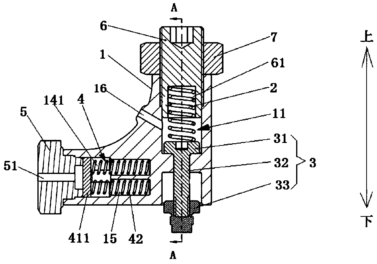
[0004] The object of the present invention is to provide an engine brake device and engine to solve the problem that the brake rocker in the prior art pushes the brake piston to brake through the stretching of the upper link and the lower link, which may easily lead to wear of the link Serious, the problem that affects the braking accuracy

Method used


Image

  • Engine brake device and engine
  • Engine brake device and engine
  • Engine brake device and engine

Examples


Embodiment Construction

[0047] The technical solutions of the present invention will be clearly and completely described below in conjunction with the accompanying drawings. Apparently, the described embodiments are some of the embodiments of the present invention, but not all of them. Based on the embodiments of the present invention, all other embodiments obtained by persons of ordinary skill in the art without making creative efforts belong to the protection scope of the present invention.

[0048] In the description of the present invention, it should be noted that the terms "center", "upper", "lower", "left", "right", "vertical", "horizontal", "inner", "outer" etc. The indicated orientation or positional relationship is based on the orientation or positional relationship shown in the drawings, and is only for the convenience of describing the present invention and simplifying the description, rather than indicating or implying that the referred device or element must have a specific orientation, ...


PUM


Abstract

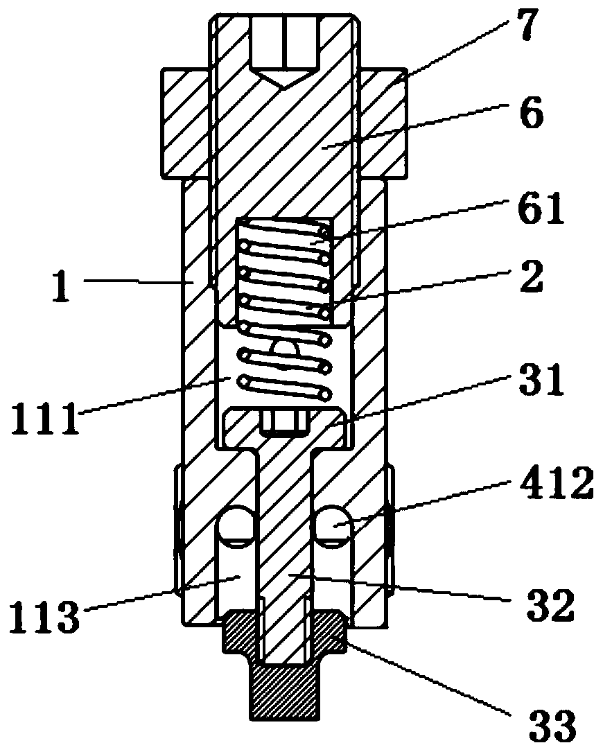
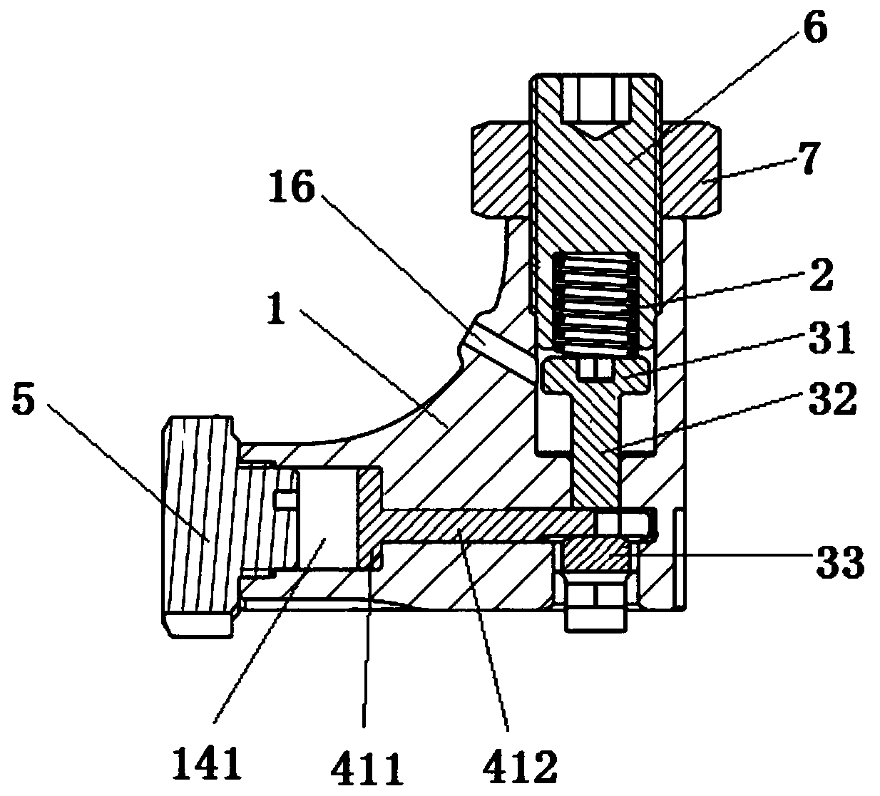
The invention relates to the technical field of engines, and particularly discloses an engine brake device and an engine. The engine brake device comprises a rocker arm, a first elastic member, a brake piston and a locking mechanism. The first elastic member is located in a guiding groove of the rocker arm. The brake piston is slidably located in the guiding groove and can abut against a valve. The brake piston is provided with a first extreme value position and a second extreme value position which are spaced. When the brake piston is located at the first extreme value position, a gas port ofthe valve is closed, the first elastic member is used for driving the brake piston to move from the first extreme value position to the second extreme value position, the valve is used for driving the brake piston to move from the second extreme value position to the first extreme value position, the locking mechanism is used for locking the position of the brake piston to the middle position between the two extreme value positions, and the brake piston cannot move after being locked, so that the gas port of the valve cannot be closed, and the engine is braked. Compared with the prior art, aconnecting rod does not need to be arranged, the abrasion condition is avoided, and thus the brake accuracy can be ensured.

Description

technical field [0001] The invention relates to the technical field of engines, in particular to an engine braking device and an engine. Background technique [0002] In the related art, when the car brakes, in addition to friction braking, the engine can also be braked to ensure that the engine will not output power to the outside. The engine braking is mostly realized by the brake rocker arm. Its working principle is that when the engine is close to the top dead center in the compression stroke, the exhaust valve is opened by a small lift under the drive of the brake rocker arm, and the compression in the cylinder The high-pressure gas is released quickly, so that the pressure in the cylinder drops rapidly, so that in the next engine power stroke, the engine will basically do no external work. [0003] In the brake rocker arm in the related art, a driving piston is set on the rocker arm, and a guide groove is also arranged on the rocker arm. The upper connecting rod, the ...

Claims


Application Information

Patent Timeline
Patent Type & Authority Applications(China)
IPC IPC(8): F01L13/06
CPCF01L13/06
Inventor 郭圣刚王刚陈广茂许成史美丽
Owner WEICHAI POWER CO LTD
Learn More