Compressor for automobile refrigeration

A technology for compressors and automobiles, applied in mechanical equipment, machines/engines, liquid fuel engines, etc., can solve the problems of damage to the inner wall of the compression chamber, large energy loss, wear of the sliding vane and the inner wall of the compression chamber, etc., to increase the service life, Improve work efficiency and reduce wear and tear

Inactive Publication Date: 2020-12-29
滁州市共赢汽车配件有限公司
View PDF0 Cites 0 Cited by
  • Summary
  • Abstract
  • Description
  • Claims
  • Application Information

AI Technical Summary

Problems solved by technology

[0003] However, the existing rotary vane compressors for automobiles still have the following deficiencies in the actual use process: due to the high-speed operation, the strong centrifugal force will cause the sliding vanes to be thrown out of the sliding vane slots and closely fit with the cylinder. When the sliding plate is worn, the sliding plate will automatically compensate, and the operating efficiency of the compressor will not be significantly affected. However, the working method between the sliding plate, the rotor and the cylinder determines that there is mechanical friction in principle inside it, and it is serious. Not only is it easy to produce a large energy loss, but also the sliding plate and the inner wall of the compression chamber will be greatly worn, so the overall efficiency and service life are low. At the same time, once the inner wall of the compression chamber is worn, the eccentrically installed rotor cannot fit the inner wall of the compression chamber. , leading to air leakage and gas compression failure; and, when the rotary vane compressor is started, the sliding vane will be thrown out by strong centrifugal force, causing the sliding vane to quickly impact the inner wall of the compression chamber, which will easily lead to compression The inner wall of the cavity is damaged, and the friction between the sliding plate and the inner wall of the compression cavity is severe, which will aggravate the damage of the inner wall of the compression cavity. Once the inner wall of the compression cavity is damaged, when it works again, it is easy to cause the compressor to jam. will cause the slider to break

Method used


Image

  • Compressor for automobile refrigeration
  • Compressor for automobile refrigeration
  • Compressor for automobile refrigeration

Examples


Embodiment Construction

[0019] The following will clearly and completely describe the technical solutions in the embodiments of the present invention with reference to the accompanying drawings in the embodiments of the present invention. Obviously, the described embodiments are only some, not all, embodiments of the present invention. Based on the embodiments of the present invention, all other embodiments obtained by persons of ordinary skill in the art without making creative efforts belong to the protection scope of the present invention.

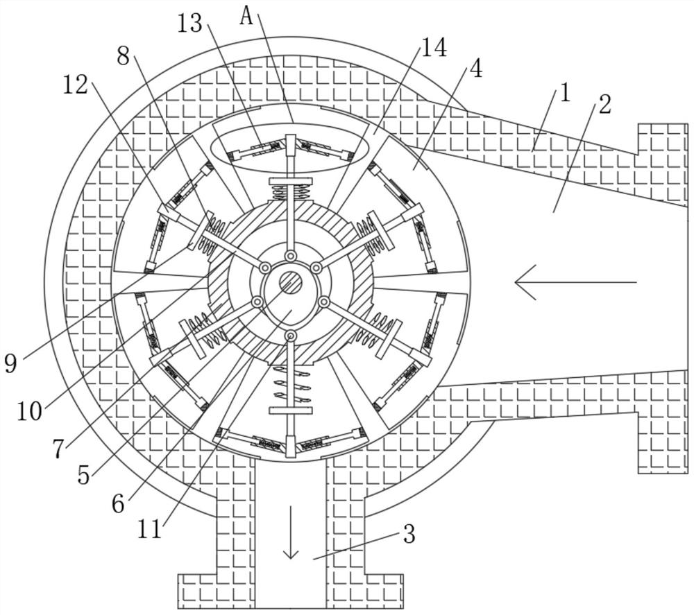
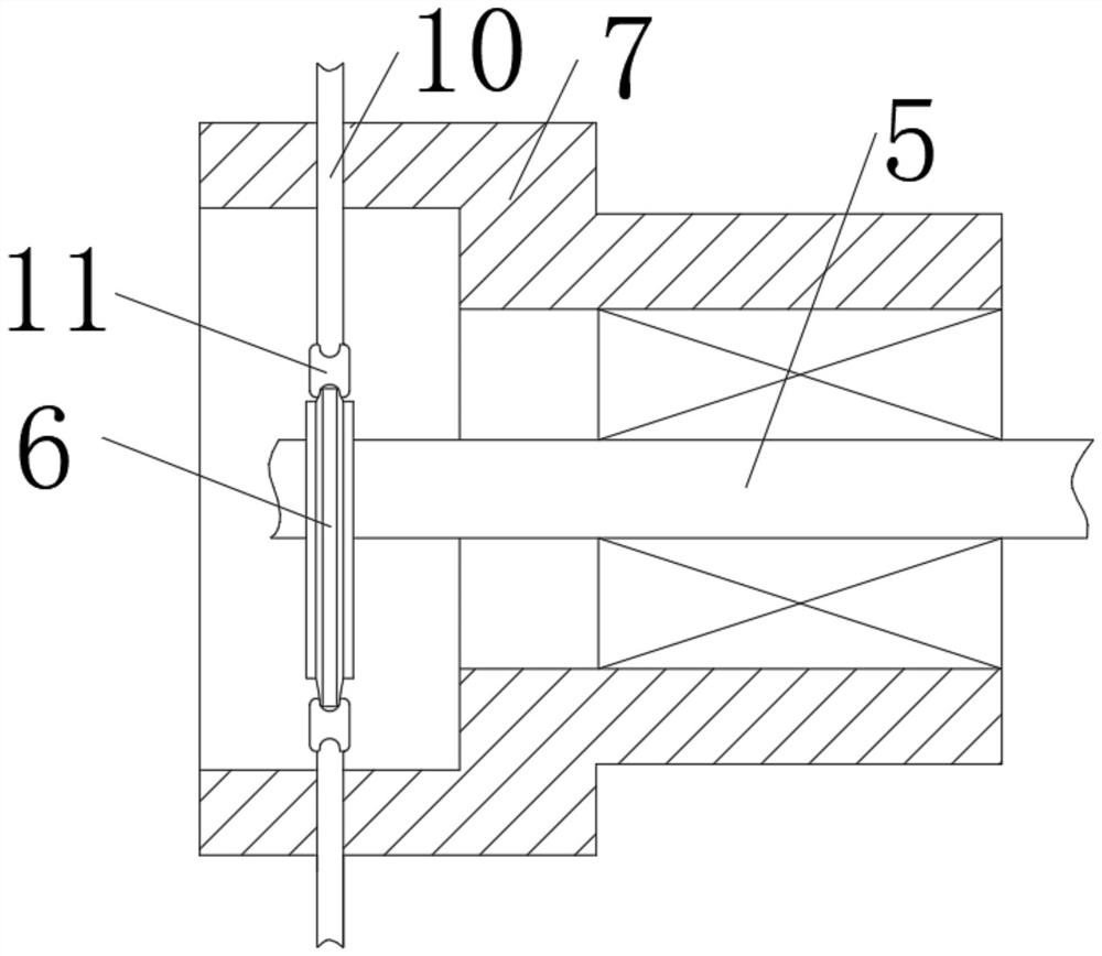
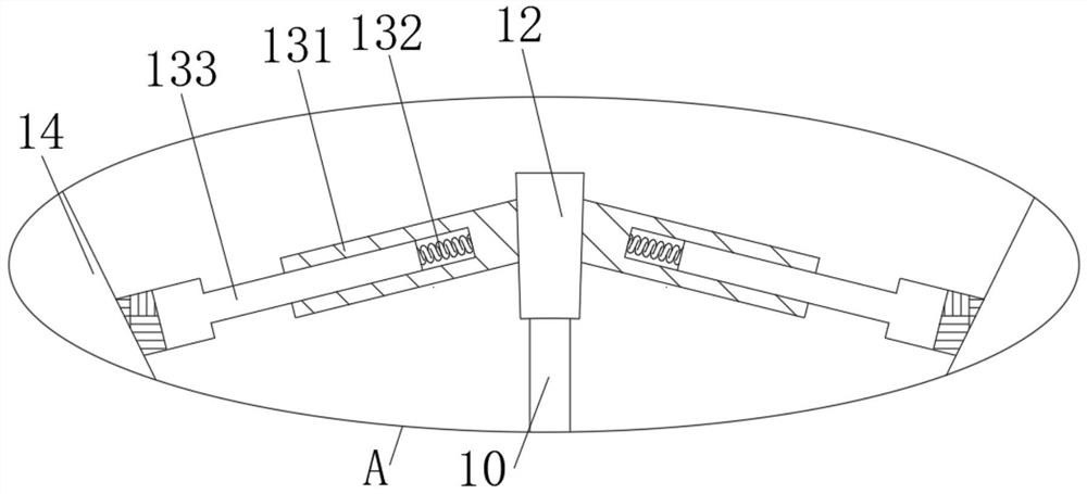
[0020] see Figure 1-4 , a compressor for automobile refrigeration, comprising a housing 1, an air inlet 2 is opened on one side of the housing 1, an air outlet 3 is fixedly connected to the bottom of the housing 1, and a compression chamber 4 is opened inside the housing 1, The middle part of the compression chamber 4 is provided with a fixed shaft 5 fixedly connected with the housing 1, one end of the fixed shaft 5 is fixedly connected with a cam 6, and the ...


PUM


Abstract

The invention relates to the technical field of air compression equipment, and discloses a compressor for automobile refrigeration. The compressor comprises a shell, an air inlet is formed in one sideof the shell, an air outlet is fixedly connected to the bottom of the shell, and a compression cavity is formed in the shell. By arranging a cam, a rolling wheel and a pressing plate device, when a supporting rod rotates, the rolling wheel can roll along the outer edge of the cam, so that the supporting rod overcomes the pull force of a reset spring to do reciprocating motion, and gas in each space separated by limiting rotary vanes is compressed; and compared with a traditional eccentric rotor and a sliding piece, the situation that the side wall of a compression cavity and the sliding pieceare seriously abraded due to various mechanical friction is avoided, the pressing plate device cannot impact the side wall of the compression cavity during gas compression work, the situation that the side wall of the compression cavity is broken is avoided, the working efficiency of the compressor is improved, and the service life of the compressor is prolonged.

Description

technical field [0001] The invention relates to the technical field of air compression equipment, in particular to a compressor for automobile refrigeration. Background technique [0002] The compressor is the heart of the automotive air-conditioning refrigeration system, which plays the role of suction, compression, and circulation pump. It mainly sucks the refrigerant from the low-pressure side, compresses it, raises its temperature and pressure, then pumps it into the high-pressure side, and reciprocates. There are two types of compressors commonly used in automobiles: rotary vane type and plunger type. Among them, rotary vane compressors are more commonly used in rotary vane compressors. Rotary vane compressors are also called sliding vane compressors and rotary vane compressors. As the name implies, they are A compressor that realizes gas compression by rotating blades, and finally converts mechanical energy into wind energy. It mainly rotates through an eccentrically ...

Claims


Application Information

Patent Timeline
Patent Type & Authority Applications(China)
IPC IPC(8): F04C29/00F04C18/30
CPCF04C18/30F04C29/00
Inventor 操龙俊
Owner 滁州市共赢汽车配件有限公司
Why Eureka
Try Eureka