Combined reciprocating vane and axial vane pump thereof

A reciprocating and combined technology, applied in the direction of rotary piston/oscillating piston pump components, rotary piston pumps, pumps, etc., can solve the problem of not being able to guarantee the performance of the sliding vane pump, affecting the normal operation of the Disc pump service life and other issues

Pending Publication Date: 2021-06-04
河北双达石油设备制造有限公司
View PDF5 Cites 0 Cited by
  • Summary
  • Abstract
  • Description
  • Claims
  • Application Information

AI Technical Summary

Problems solved by technology

However, the sliding vane pumps currently on the market are mainly radial sliding vane pumps, which mainly install multiple sliding vanes directly in the radial grooves of the rotor, so that when the rotor is rotating, the sliding vanes are in the radial sliding vane grooves. Do radial reciprocating motion, so that the slide body will be worn, especially during the radial movement of the slide, it will also form a sliding motion with the inner wall of the pump. Due to the high sliding speed, the slide will be severely worn, often The sliding vane needs to be repaired or replaced, otherwise it cannot guarantee the performance of the sliding vane pump, which not only affects the stability of the sliding vane pump, but also affects the normal operation of the entire sliding vane pump. At the same time, the sliding vane in the pump body is constantly Replacement will not only increase the repair cost, but also reduce the service life of the sliding vane pump

Method used


Image

  • Combined reciprocating vane and axial vane pump thereof
  • Combined reciprocating vane and axial vane pump thereof
  • Combined reciprocating vane and axial vane pump thereof

Examples


Embodiment Construction

[0022] The following will clearly and completely describe the technical solutions in the embodiments of the present invention with reference to the accompanying drawings in the embodiments of the present invention. Obviously, the described embodiments are only some, not all, embodiments of the present invention. Based on the embodiments of the present invention, all other embodiments obtained by persons of ordinary skill in the art without making creative efforts belong to the protection scope of the present invention.

[0023] In order to make the above objects, features and advantages of the present invention more comprehensible, the present invention will be further described in detail below in conjunction with the accompanying drawings and specific embodiments.

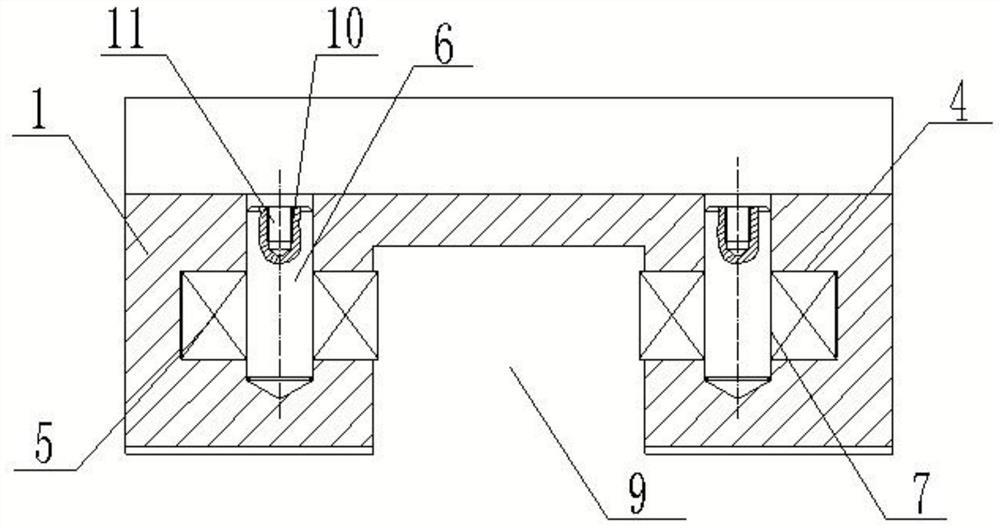
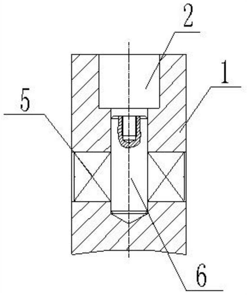
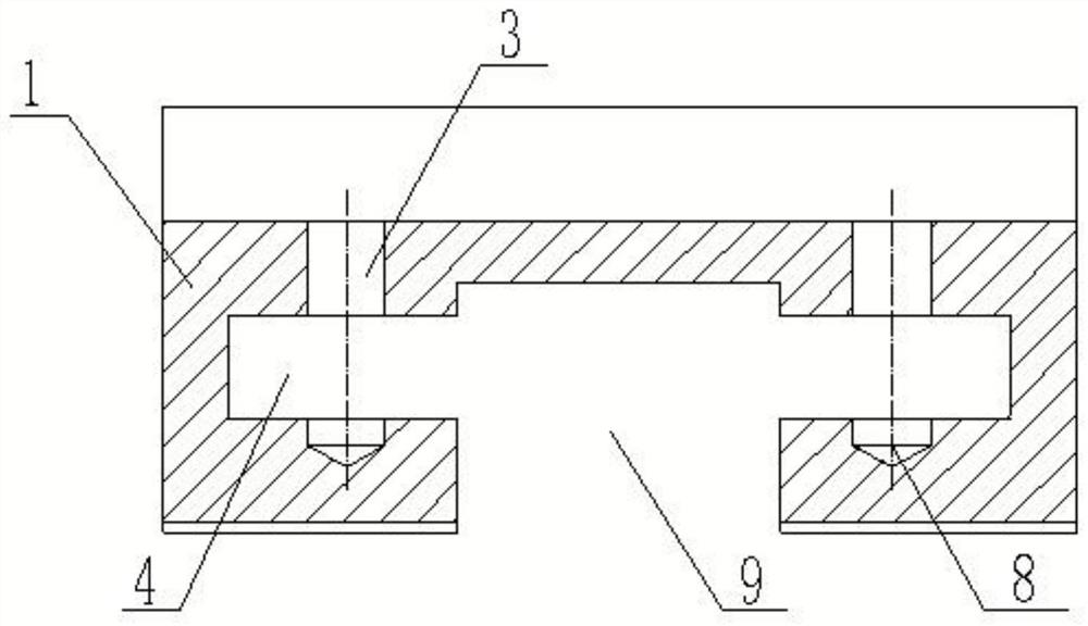
[0024] Such as Figure 1-3 As shown, the present invention provides a combined reciprocating slider, which includes a slider body 1, and a third groove 4 is symmetrically opened on the slider body 1, and a rolling...


PUM


Abstract

The invention discloses a combined reciprocating vane. The combined reciprocating vane comprises a vane body, third grooves are symmetrically formed in the vane body, rolling assemblies are detachably connected in the third grooves, a first groove is formed in the top of the vane body, first through holes are symmetrically formed in the lower groove wall of the first groove, second through holes are formed in the rolling assemblies, first blind holes are formed in the lower groove walls of the third grooves, the hole center of each first through hole, the hole center of each second through hole and the hole center of each first blind hole are located on the same center line, supporting shafts are connected into the first through holes, the second through holes and the first blind holes in an inserted mode, and a second groove is formed between the two third grooves. According to the combined reciprocating vane, the sealing surface in contact with rotors is designed into rolling motion, so that abrasion caused by sliding motion generated by the sealing surface in contact with the rotors can be prevented, and the product reliability is improved; and the combined reciprocating vane is simple in structure and convenient to mount and dismount, the maintenance cost is reduced, and the service life of an axial vane pump can be prolonged.

Description

technical field [0001] The invention relates to the technical field of sliding vane pumps, in particular to a combined reciprocating sliding vane and an axial sliding vane pump thereof. Background technique [0002] Sliding vane pumps are also called vane pumps, scraper pumps, and scraper pumps. Most consist of a pump body, rotor, stator, pump cover, and multiple vanes. Its working principle is to rely on centrifugal force to make the sliding vanes close to the eccentric stator, the cavity between the two sliding vanes at the inlet increases to absorb liquid, and the cavity between the two sliding vanes at the outlet decreases to discharge liquid. Wherein the rotor 17 is a cylinder with a plurality of radial grooves, and sliding vanes are placed in the slots, and the sliding vanes can slide freely in the slots. The rotor is placed eccentrically in the pump body. When the rotor is driven by the prime mover to rotate, the sliding vanes are pressed against the inner wall of t...

Claims


Application Information

Patent Timeline
Patent Type & Authority Applications(China)
IPC IPC(8): F04C2/344F04C15/00
CPCF04C2/3448F04C15/00F04C2240/20
Inventor 李博建张生昌梁志宏
Owner 河北双达石油设备制造有限公司
Why Eureka
Try Eureka