
System, method and device for monitoring terminal equipment

A technology of terminal equipment and equipment, which is applied in the field of data processing and can solve problems such as wasting time

Inactive Publication Date: 2019-08-16
JIANGSU JINHENG INFORMATION TECH CO LTD
View PDF3 Cites 2 Cited by
  • Summary
  • Abstract
  • Description
  • Claims
  • Application Information

AI Technical Summary

Problems solved by technology

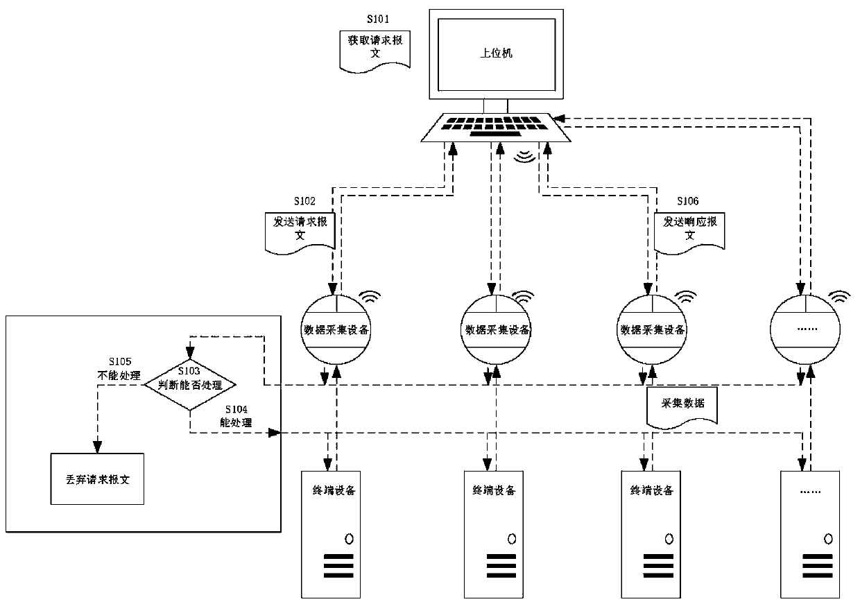
[0006] This application provides a system, method and device for monitoring terminal equipment, which can be used to solve the technical problem in the prior art that requires manpower to check out request messages that have not received response messages, resulting in a waste of time

Method used


Image

  • System, method and device for monitoring terminal equipment
  • System, method and device for monitoring terminal equipment
  • System, method and device for monitoring terminal equipment

Examples


Embodiment Construction

[0072] In order to make the purpose, technical solution and advantages of the present application clearer, the implementation manners of the present application will be further described in detail below in conjunction with the accompanying drawings.

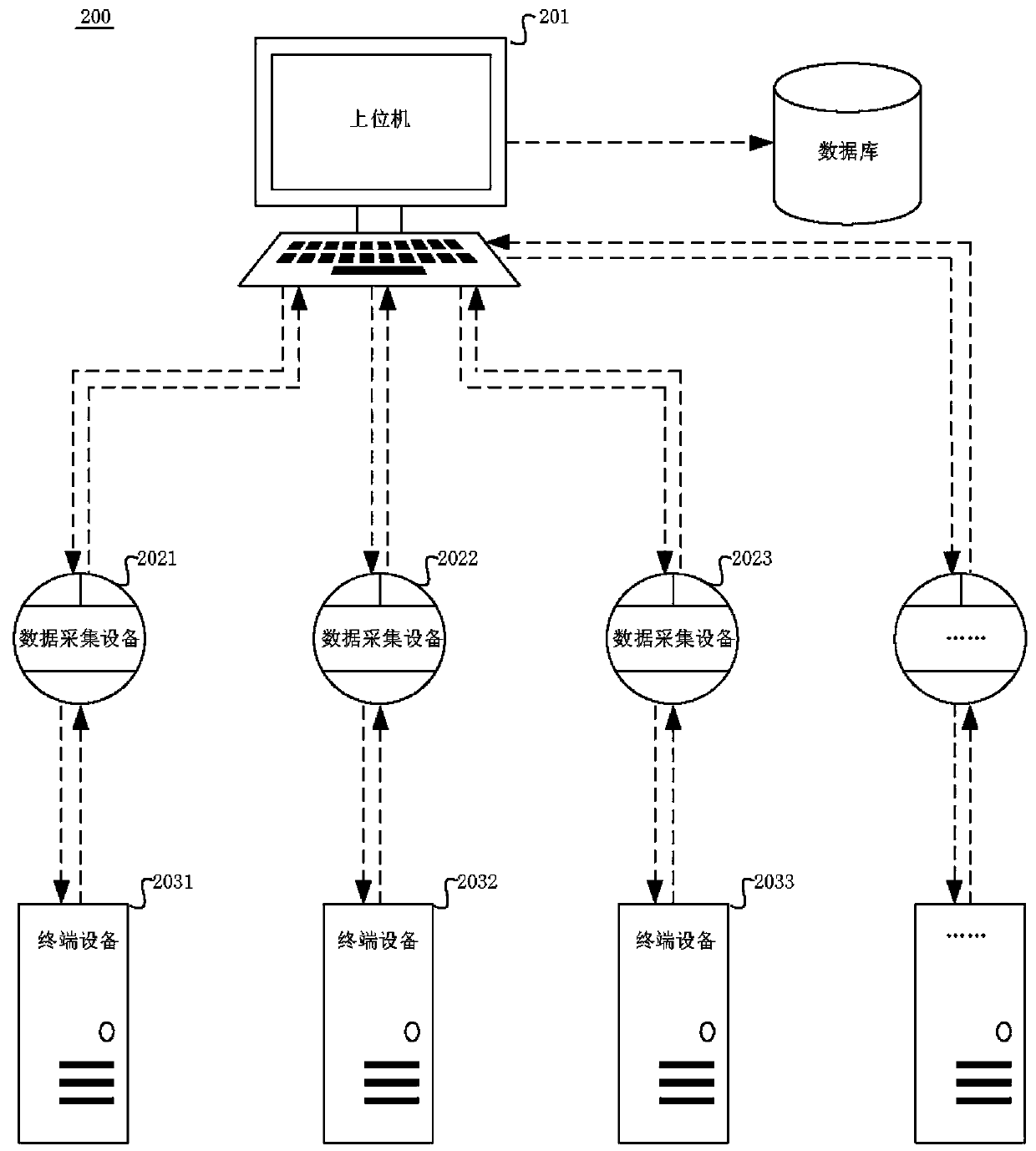
[0073] First combine the following Figure 2a A possible system architecture applicable to the embodiments of the present application is introduced.

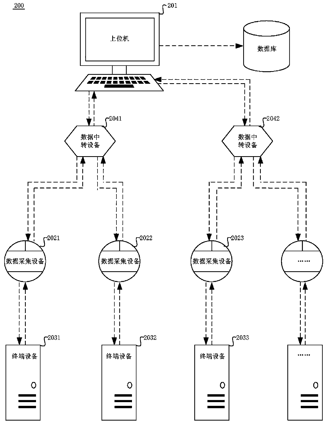
[0074] Please refer to Figure 2a , which exemplarily shows a schematic structural diagram of a system for monitoring terminal equipment applicable to the embodiment of the present application. The system 200 may include a host computer 201, a plurality of data acquisition devices, for example, Figure 2a The data collection device 2021, the data collection device 2022 and the data collection device 2023 shown in, and a plurality of terminal devices, for example, Figure 2a Terminal device 2031 , terminal device 2032 and terminal device 2033 shown in FIG.

[0075] Wherein, the ...


PUM


Abstract

The embodiment of the invention provides a system, method and device for monitoring terminal equipment. The system comprises an upper computer, a plurality of data acquisition devices and a pluralityof terminal devices. The upper computer can be used for generating a request message and a first message identifier and storing the first message identifier; and after the request message is sent, waiting for a preset time period, receiving a response message carrying a second message identifier, and if it is determined that a target message identifier which cannot correspond to the second messageidentifier exists in the first message identifier, determining that a response message corresponding to the request message carrying the target message identifier is not received. In the embodiment of the invention, the upper computer can quickly screen out the response message which is not returned in time, so that the specific fault can be found, analyzed and positioned for the response messagewhich is not returned in time, the operation and maintenance personnel can conveniently and timely master the operation condition of the equipment, and the monitoring efficiency of the terminal equipment is improved.

Description

technical field [0001] The present application relates to the technical field of data processing, and in particular to a system, method and device for monitoring terminal equipment. Background technique [0002] In the iron and steel industry, automatic production is inseparable from the monitoring of the performance of each production equipment in the factory, and the performance data of each production equipment obtained through monitoring is usually transmitted through the network. [0003] A data transmission method in the prior art is that after sending the first request message, the second request message will be sent only after receiving the response message of the request message, and then the second request message will be sent after receiving the second request message. After the response message of the first request message, the third request message will occur, and so on. However, the number of production equipment involved in the actual production process is hu...

Claims


Application Information

Patent Timeline
Patent Type & Authority Applications(China)
IPC IPC(8): H04L12/24H04L12/26
CPCH04L41/0631H04L41/0677H04L41/0681H04L43/0817H04L43/16
Inventor 孙茂杰李福存张楠谷庆俞洁辛治宏陈琦
Owner JIANGSU JINHENG INFORMATION TECH CO LTD
Learn More