Eureka AIR delivers breakthrough ideas for toughest innovation challenges, trusted by R&D personnel around the world.

Welding quality monitoring system and method

A welding quality and monitoring system technology, applied in welding equipment, laser welding equipment, metal processing equipment, etc., can solve problems such as inaccurate welding quality

Active Publication Date: 2015-07-01
BC P INC CHINA NAT PETROLEUM CORP +2
View PDF7 Cites 34 Cited by
  • Summary
  • Abstract
  • Description
  • Claims
  • Application Information

AI Technical Summary

Problems solved by technology

[0004] Aiming at the problems existing in the prior art, the embodiment of the present invention provides a welding quality monitoring system and method, which is used to solve the technical problems in the prior art that the manual observation of the welding quality is inaccurate and the human body cannot be avoided by the high-energy laser

Method used


Image

  • Welding quality monitoring system and method
  • Welding quality monitoring system and method
  • Welding quality monitoring system and method

Examples


Embodiment 1

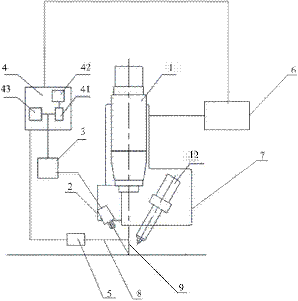
[0035] This embodiment provides a welding quality monitoring system, such as figure 1 As shown, the system includes: a welding torch 1, an infrared thermal imager 2, an image acquisition card 3, and an image processing computer 4; wherein,

[0036] The welding torch 1 is used to weld the welding spot; the welding torch 1 includes: a laser welding torch 11 and an arc welding torch 12 .

[0037] The thermal imaging camera 2 is used to record the molten pool infrared thermal imaging data of the welding spot and the welding seam forming process during the welding process of the welding torch 1;

[0038] After the infrared thermal imager 2 has recorded the infrared thermal imaging data of the melting pool and the welding seam forming process, the image acquisition card 3 is specifically used for: collecting the infrared thermal imaging data of the molten pool and welding seam forming process, sending the welding seam forming process of the molten pool infrared thermal imaging data...

Embodiment 2

[0088] Corresponding to Embodiment 1, this embodiment also provides a welding quality monitoring method, such as Figure 4 As shown, the method includes the following steps:

[0089] Step 410, using a welding torch to weld the spot;

[0090] In this step, the welding torch includes a laser welding torch and an arc welding torch.

[0091] Step 411, recording infrared thermal imaging data of the molten pool of the solder joint;

[0092] In this step, during the welding process of the welding torch, an infrared imager is used to record the infrared thermal imaging data of the molten pool of the welding spot and the welding seam forming process.

[0093] Step 412, collecting and sending the infrared thermal imaging data of the melting pool;

[0094] After the infrared thermal imager has recorded the infrared thermal imaging data of the molten pool and the weld forming process, the image acquisition card is used to collect the infrared thermal imaging data of the molten pool and...


PUM

PropertyMeasurementUnit
Thicknessaaaaaaaaaa

Abstract

The invention provides a welding quality monitoring system and method. The welding quality monitoring system comprises a welding gun, a thermal infrared imager, an image capture card and an image processing computer. The welding gun is used for welding welding spots. The thermal infrared imager is used for recording molten bath infrared thermal imaging data of the welding spots. The image capture card is used for collecting the molten bath infrared thermal imaging data and sending the molten bath infrared thermal imaging data to the image processing computer. The image processing computer is used for analyzing the molten bath infrared thermal imaging data to obtain welding parameters, comparing the welding parameters with preset welding standards and obtaining a welding spot quality estimation result. In this way, by the adoption of the welding quality monitoring system and method, online monitoring of automatic welding quality can be achieved, the monitoring efficiency and monitoring quality are improved, and the missing inspection rate is reduced.

Description

technical field [0001] The invention belongs to the technical field of petroleum engineering, and in particular relates to a welding quality monitoring system and method. Background technique [0002] The laser / arc hybrid welding technology has the advantages of fast welding speed, large welding penetration, good bridging ability, good weld mechanical properties, thick primary welding layer, and saving welding consumables. However, the welding equipment system of laser / arc hybrid welding is huge and the structure is complex. Many parameters such as arc voltage, wire feeding speed, laser energy, laser defocus, laser incident angle, and light wire spacing will affect the welding forming effect and welding quality. Therefore, online monitoring of welding process quality is required. [0003] At present, the automatic welding equipment of pipelines monitors the welding quality online by manual direct observation. On the one hand, this monitoring method cannot adapt to the high ...

Claims


Application Information

Patent Timeline
IPC IPC(8): B23K26/70B23K26/348
CPCB23K26/348
Inventor 檀朝彬曾惠林皮亚东贾世民刘然张倩梁天军郭启超
Owner BC P INC CHINA NAT PETROLEUM CORP
Why Eureka
Eureka Blog
Learn More